Zero backflow vent for liquid helium cooled magnets

a technology of liquid helium cooled magnets and backflow vents, which is applied in the field of superconducting magnets, can solve the problems of high pressure buildup of helium gas in the cryostat, potentially dangerous conditions for medical staff and patients, and high cost, and achieve the effect of removing magnet icing

Inactive Publication Date: 2005-04-28
GE MEDICAL SYST GLOBAL TECH CO LLC
View PDF12 Cites 19 Cited by
  • Summary
  • Abstract
  • Description
  • Claims
  • Application Information

AI Technical Summary

Benefits of technology

[0007] The zero-backflow vent system of the present invention prevents backflow into the magnet liquid helium vessel and therefore eliminates magnet icing. The present invention opens in the event of a magnet quench, but closes after pressure is relieved. In general, the present invention employs a ...

Problems solved by technology

In the event of an undesired magnet quench or reversion of the magnet to a non-superconductive state, however, the rapid and potentially dangerous high pressure buildup of helium gas in the cryostat requires pressure relief through r...

Method used


Image

  • Zero backflow vent for liquid helium cooled magnets
  • Zero backflow vent for liquid helium cooled magnets
  • Zero backflow vent for liquid helium cooled magnets

Examples


Embodiment Construction

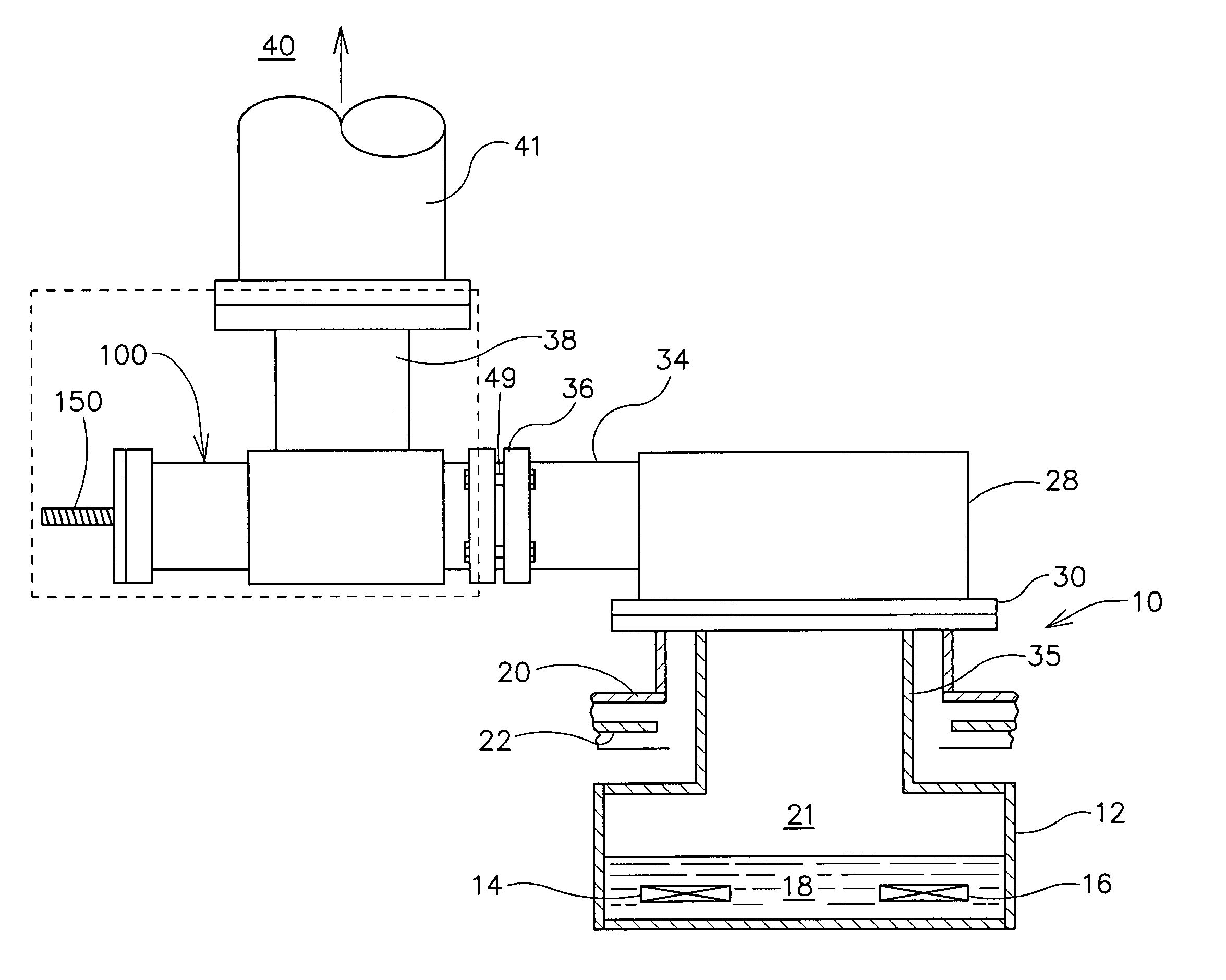
[0014] Referring now to the drawings in detail, wherein like numbered elements correspond to like elements throughout, FIG. 1 illustrates a recondensing superconducting magnet system, generally identified 10. The system 10 includes a cryostat or helium pressure vessel 12 (when liquid helium is the cryogen), which vessel 12 is shown schematically in reduced size and which encloses a plurality of magnet coils 14, 16 in liquid helium 18. The helium pressure vessel 12 is enclosed within a surrounding vacuum vessel 20 and intermediate members such as a thermal radiation shield 22. Helium gas 21 forms above the liquid helium 18 through the boiling of the liquid helium 18 in providing cryogenic temperatures to the superconducting magnet system 10. In this fashion, the extreme cold maintains current flow through the magnet coils 14, 16 after a power source, which source is initially connected to the coils 14, 16, is disconnected due to the absence of electrical resistance of the cold magnet...


PUM


Abstract

The zero-backflow vent assembly (100) of the present invention prevents backflow into the magnet cryogen vessel (12) and therefore eliminates magnet icing. In general, the present invention employs a spring loaded valve in the magnet vent turret (38) to prevent the influx of air after a magnet quench event. The magnet vent turret (38) is the interface between the liquid helium vessel (12) in the magnet and the atmosphere (40). A vent stack is employed to channel any cryogenic exhaust gas out of the room, normally to the outside atmosphere (40).

Description

BACKGROUND OF THE INVENTION [0001] The present invention relates generally to superconducting magnets, and more particularly to an assembly for preventing ambient air from flowing back into a superconducting magnet following magnet quench or burst disk failure. [0002] As is well known, a magnet can be made superconductive by placing it in an extremely cold environment, such as by enclosing it in a cryostat or pressure vessel containing a cryogen. This extremely cold environment effectively reduces resistance in the magnet coils to negligible levels, such that when a power source is initially connected to the coil to introduce a current flow through the coils, the current will continue to flow through the coils even after power is removed, thereby maintaining a magnetic field. Such a magnetic field finds wide application in the field of magnetic resonance imaging (MRI). The cryogen most often used with MRI superconducting magnets is helium, which exists in a liquid state at approxima...

Claims


Application Information

Patent Timeline
IPC IPC(8): G01R33/3815H01F6/00H01F27/14H01F27/40
CPCG01R33/3815H01F27/402H01F27/14H01F6/00
Inventor MANGANO, ROY A.MCGUINNESS, KATHLEEN W.ZHANG, LIMIN
Owner GE MEDICAL SYST GLOBAL TECH CO LLC
Why Eureka
Try Eureka