Mobile communication terminal with RFID function and RFID programming method in the same

Inactive Publication Date: 2005-04-28
SAMSUNG ELECTRONICS CO LTD
View PDF15 Cites 123 Cited by
  • Summary
  • Abstract
  • Description
  • Claims
  • Application Information

AI Technical Summary

Benefits of technology

[0018] It is, therefore, an object of the present invention to provide a method for

Problems solved by technology

Therefore, when signal degradation occurs due to a change in an RF environment, the contactless programming scheme is difficult to support stable programming.
Although U.S. Pat. No. 5,712,628 discloses a system applicable to various radio frequencies and signal formats, a ci

Method used


Image

  • Mobile communication terminal with RFID function and RFID programming method in the same
  • Mobile communication terminal with RFID function and RFID programming method in the same
  • Mobile communication terminal with RFID function and RFID programming method in the same

Examples


Embodiment Construction

[0031] Preferred embodiments of the present invention will now be described in detail with reference to the annexed drawings. In the drawings, the same or similar elements are denoted by the same reference numerals even though they are depicted in different drawings. In the following description, a detailed description of known functions and configurations incorporated herein has been omitted for conciseness.

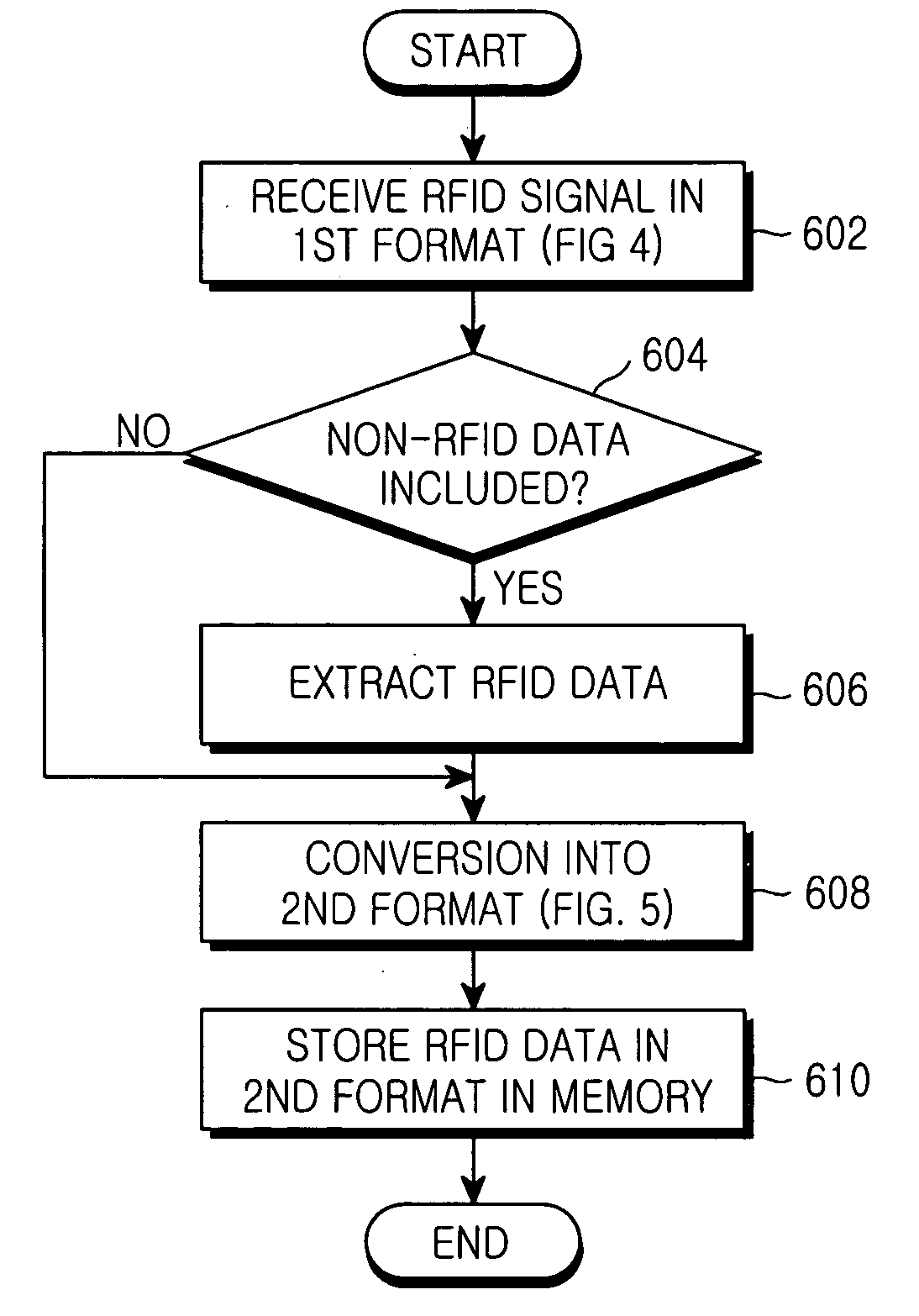
[0032] In the following description, the term “RFID programming” indicates an operation of newly storing or updating RFID data provided from the exterior (base station, server, host computer, user, etc.) in a memory so that a mobile communication terminal can perform an RFID function.

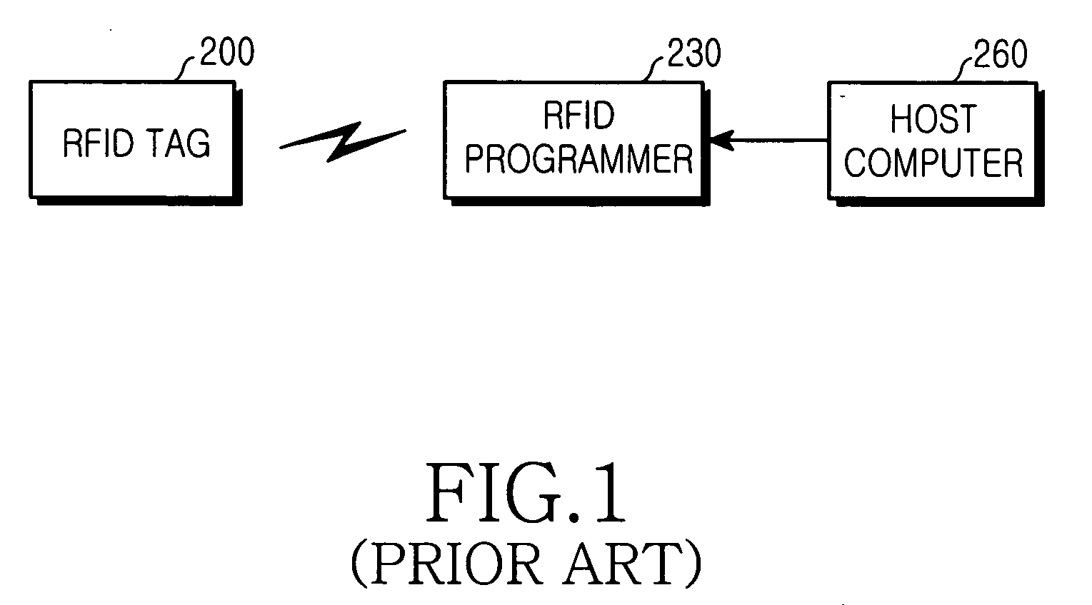
[0033]FIG. 3A is a block diagram illustrating a structure of an RFID tag programming system according to an embodiment of the present invention. Referring to FIG. 3A, a mobile communication terminal 102 receives RFID-related information to be newly stored or updated, from a host computer 104, and ...


PUM


Abstract

A mobile communication terminal including a radio frequency identification (RFID) receiver for receiving RFID data in a first format. An operation device converts the RFID data in the first format into a second format. A memory stores the RFID data in the second format. A codec encodes RFID data stored in the memory. A modulator RFID-modulates data output from the codec. An RFID transmitter transmits data output from the modulator to an RFID reader.

Description

[0001] This application claims priority under 35 U.S.C. § 119 to an application entitled “Mobile Communication Terminal With RFID Function and RFID Programming Method In the Same” filed in the Korean Intellectual Property Office on Oct. 28, 2003 and assigned Ser. No. 2003-75652, the contents of which are incorporated herein by reference. BACKGROUND OF THE INVENTION [0002] 1. Field of the Invention [0003] The present invention relates generally to a mobile communication terminal, and in particular, to a mobile communication terminal with a radio frequency identification (RFID) function and an RFID programming method in the same. [0004] 2. Description of the Related Art [0005] The U.S. National Laboratory for Department of Agriculture developed an RFID transponder, or an RFID tag, for identifying livestock. An RFID flag, in which an electric code capable of identifying an animal is recorded, is inserted or attached to the animal. An interrogator (or a reader) for reading the electric ...

Claims


Application Information

Patent Timeline
IPC IPC(8): H04B5/02G06K7/00G06K19/07H04B1/59H04M1/72412
CPCG06K7/0008H04M1/7253G06K19/0723G06K7/10297H04M1/72412H04B5/02
Inventor JEI, DAE-GUNN
Owner SAMSUNG ELECTRONICS CO LTD
Why Eureka
Try Eureka