
Powerless type security device

a security device and power source technology, applied in the direction of alarm locks, alarm mechanical vibrations, instruments, etc., can solve the problems of inability to determine the specific opening or closing position, the installation cost or the construction cost is extremely high, and the running cost is undetectabl

Inactive Publication Date: 2005-04-28
USC
View PDF4 Cites 15 Cited by
  • Summary
  • Abstract
  • Description
  • Claims
  • Application Information

AI Technical Summary

Benefits of technology

[0013] In order to achieve the above-described objects, the invention defined in claim 1 concerns a non-power source type monitor device in a non-power source type security device in which a power of the security device for monitoring whether the door or the window of a building is opened or closed, whether a person enters or exits from a building or a room, or whether a vehicle parks in or leaves from a parking place is supplied by a piezoelectric power generating device using a piezoelectric ceramics member. The piezoelectric power generating device generates power by applying a distortion deformation to the piezoelectric ceramics member. The piezoelectric power generating device comprises: a pair of piezoelectric ceramics members; a cushion material for holding each of the piezoelectric ceramics members under a soft state in which the natural oscillation of each piezoelectric ceramics member is hardly transmitted to other structural members; a pendul...

Problems solved by technology

When the usual security devices are attached to all the windows or the doors of one house, a facility cost or a construction cost is extremely increased.
Thus, a running cost is undesirably increased.
Still further, in the usual security device, a plurality of the same kinds of devices needs to be attached, so that a specific opening or closing position is hardly instantaneously decided.
Accordingly, the usual security device has great many problems to be solved in practice.
The above-described problems are common to those of a monitor device for monitoring the entrance to or exit from the building or the room, or a device for monitoring a parking or leaving state in a parking place.
However, although the practicability of the usual PZT type piezoelectric ceramics element is anticipated, a quantity of generated energy is very small.
Thus, the usual PZT type piezoelectric ceramics element is undesirably deficient in its practicability.
This problem arises, because the piezoelectric power generating device using the piezoelectric ceramics element of this type has important factors, for instance, the natural oscillation of the piezoelectric ceramics plate essentially needs to be continued as long as possible and how a strong and effective impact force is applied to the piezoelectric ceramics element.
However, most of the usual piezoelectric power generating devices do not have a support structure that- the natural oscillation of the piezoelectric ceramics element plate does not accompany a mechanical resistance and a structure that the impact force to the piezoelectric ceramics element is still applied by steel balls as disclosed in, for instance, Japanese Patent Application Laid-Open No. 2001-145375.

Method used


Image

  • Powerless type security device
  • Powerless type security device
  • Powerless type security device

Examples


first embodiment

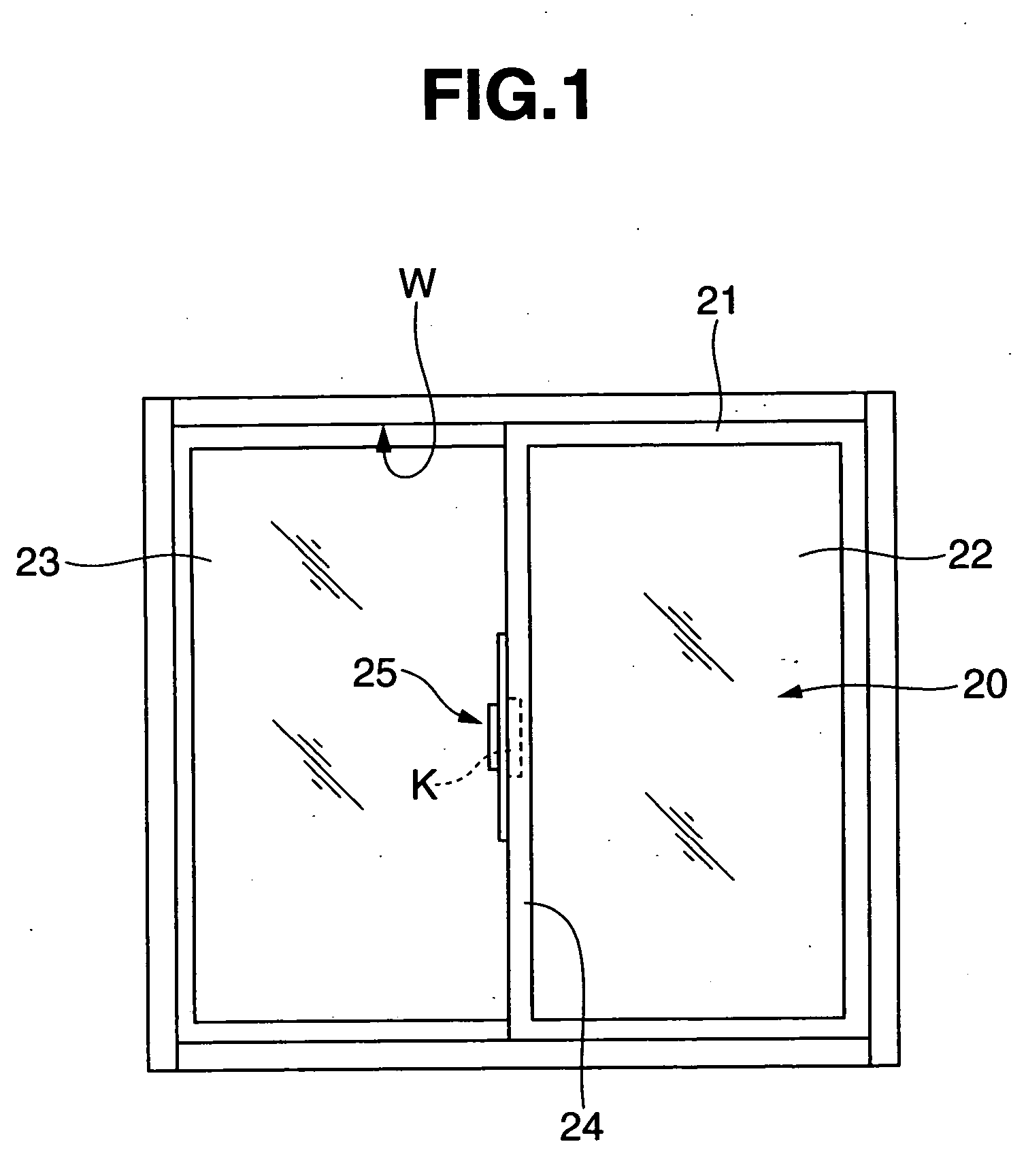
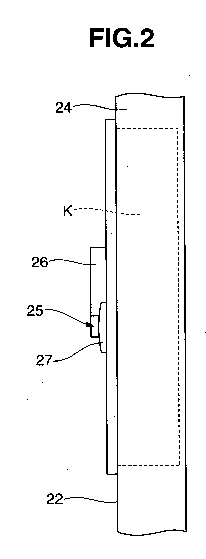
[0029] In a basic form of the window 20 two sliding doors 22 and 23 are fitted to a substantially square shaped window frame 21 made of an aluminum sash as a frame fixed to the building so as to freely slide in a mirror-image manner. A crescent lock 25 provided with the monitor device K is arranged on an inner vertical frame part 24 of the sliding door 22 so as to be detachably engaged with an engaging member (not shown) disposed in the other sliding door 23. The monitor device K is provided to operate interlocking with the opening and closing operation of the window 20 to detect the opening and closing operations of the window 20.

[0030] The basic structure of the crescent lock 25 includes, as shown in FIG. 2, an operating lever part 26 and a substantially semicircular engaging part 27 connected to the operating lever part 26 and held to freely rotate on a shaft as a center of rotation. The engaging part 27 is rotated by holding the operating lever part 26 to engage the engaging pa...

second embodiment

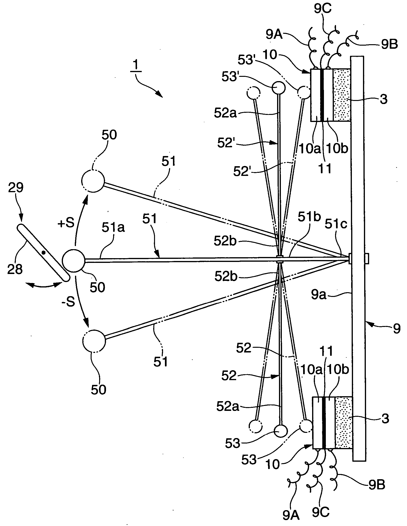
[0055] In the second embodiment, a case that the vertical elastic members 52A and 52B are connected to the base member 51A by welding is described as an example, however, the present invention is not limited thereto. The elastic members may be connected integrally to the base member by known means such as screwing, caulking, or the use of a strong adhesive or soldering.

[0056] Further, in each of the embodiment, a case that the piezoelectric power generating device according to the present invention is attached to the crescent lock 20 for monitoring the opening and closing of the window W to form the monitor device is described as an example. However, the present invention is not limited thereto and the present invention may be applied various kinds of security devices for monitoring whether the door of a building is opened or closed, whether a person enters or exits from a building or a room, or whether a vehicle parks in or leaves from a parking place.

Industrial Applicability

[005...


PUM


Abstract

The present invention provides a non-power source type monitor device installed in a place where a non-power source system needs to be used or a place preferably suitable for the non-power source system, in which a quantity of generated energy not lower than several ten times as much as an output of electric current obtained by a usual piezoelectric power generating device using steel balls can be assuredly obtained by striking a piezoelectric ceramics element once and a piezoelectric power generating device is formed commonly with means capable of automatically repeatedly striking the piezoelectric ceramics element so that a quantity of generated energy of a practical level can be assuredly ensured as a power source of such type of monitor device. The structure thereof includes, in principle,

Description

TECHNICAL FIELD [0001] The present invention relates to a non-power source type security device that can detect without a power source whether the door or the window of a building is opened or closed, whether a person enters or leaves from the building or a room and whether a vehicle is parked in or leaves from a parking place by the use of a piezoelectric power generating device using a piezoelectric ceramics element. BACKGROUND ART [0002] Most of usual security devices attached to the window or the door of a building are ordinarily attached afterward to the lock part of the window or the door. These security devices are easily externally detected and the operations thereof can be intentionally stopped by breaking glass or the door. [0003] Further, in such usual security devices, the wiring of a power source for operation needs to be attached afterward. When the usual security devices are attached to all the windows or the doors of one house, a facility cost or a construction cost ...

Claims


Application Information

Patent Timeline
IPC IPC(8): E05B45/06E05B47/00E05C3/04F03G7/06F03G7/08G08B13/16H02N2/18H10N30/30
CPCE05B45/06E05B2047/0062E05B2047/0068H02N2/183F03G7/06F03G7/08G08B13/1654E05C3/046F03G5/06F03G5/062F03G7/083
Inventor SAKAI, YASUHIRO
Owner USC
Features
  • Generate Ideas
  • Intellectual Property
  • Life Sciences
  • Materials
  • Tech Scout
  • Unparalleled Data Quality
  • Higher Quality Content
  • 60% Fewer Hallucinations
Learn More