Fluid ejector pumps

a technology of ejector pumps and fluids, which is applied in the direction of machines/engines, mechanical equipment, transportation and packaging, etc., can solve the problems of increasing turbulence, achieve greater turbulence, increase vacuum or suction, and enhance turbulent mixing

Inactive Publication Date: 2005-04-28
SOLOMON JASON D
View PDF15 Cites 22 Cited by
  • Summary
  • Abstract
  • Description
  • Claims
  • Application Information

AI Technical Summary

Benefits of technology

[0010] The fluid pumps of the present invention overcome the disadvantages of prior fluid pumps utilizing flow altering deflectors. The fluid pumps of the present invention enhance turbulent mixing of air and water flowing through the pumps, create a high-low mixing effect of fluid flowing through the flow passage of the pumps, create greater turbulence in the fluid flowing through the flow passage of the pumps, increase vacuum or suction produced at a suction inlet o

Problems solved by technology

As the fluid flowing through the flow passage encounters the defle

Method used


Image

  • Fluid ejector pumps
  • Fluid ejector pumps
  • Fluid ejector pumps

Examples


Embodiment Construction

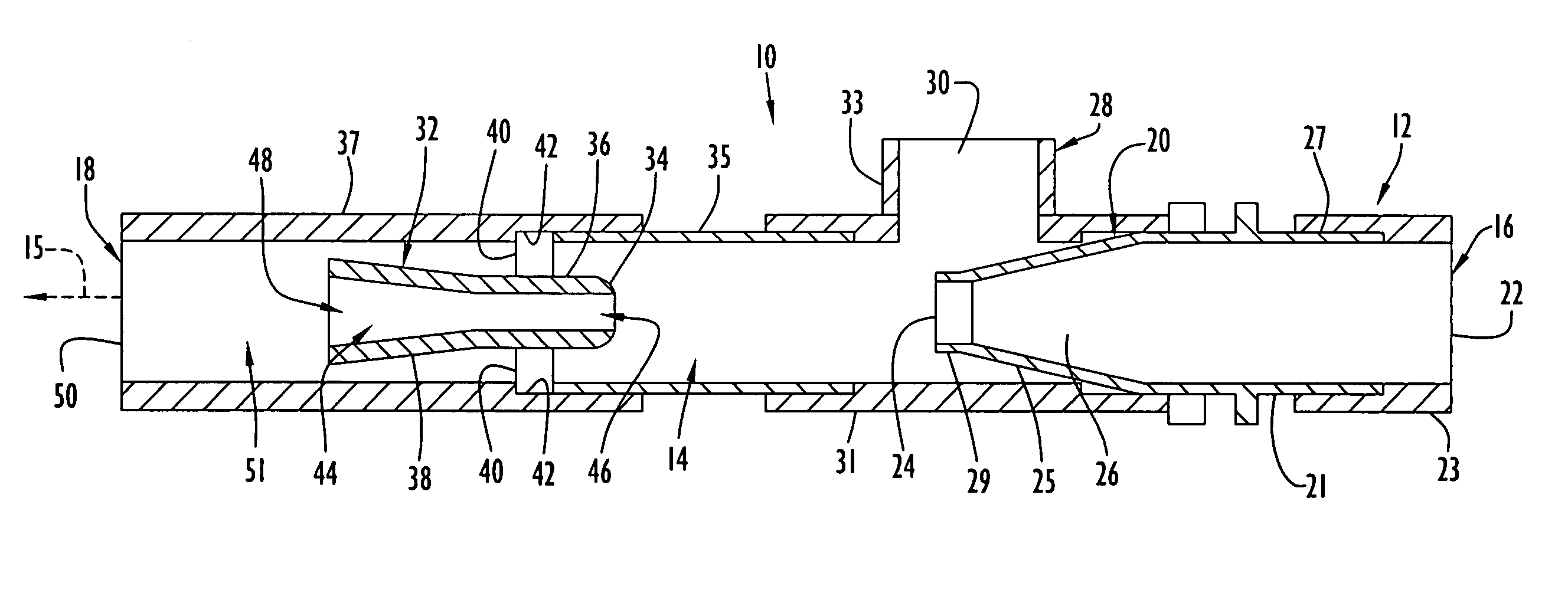
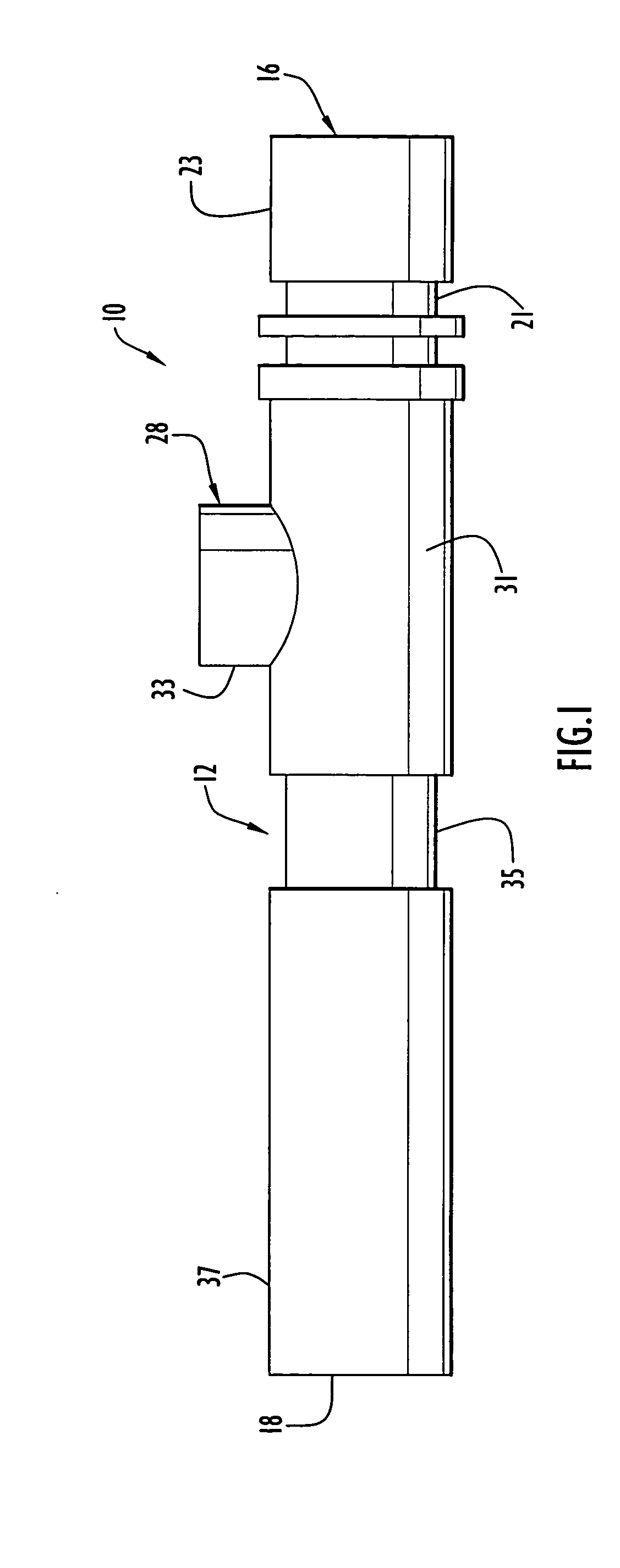
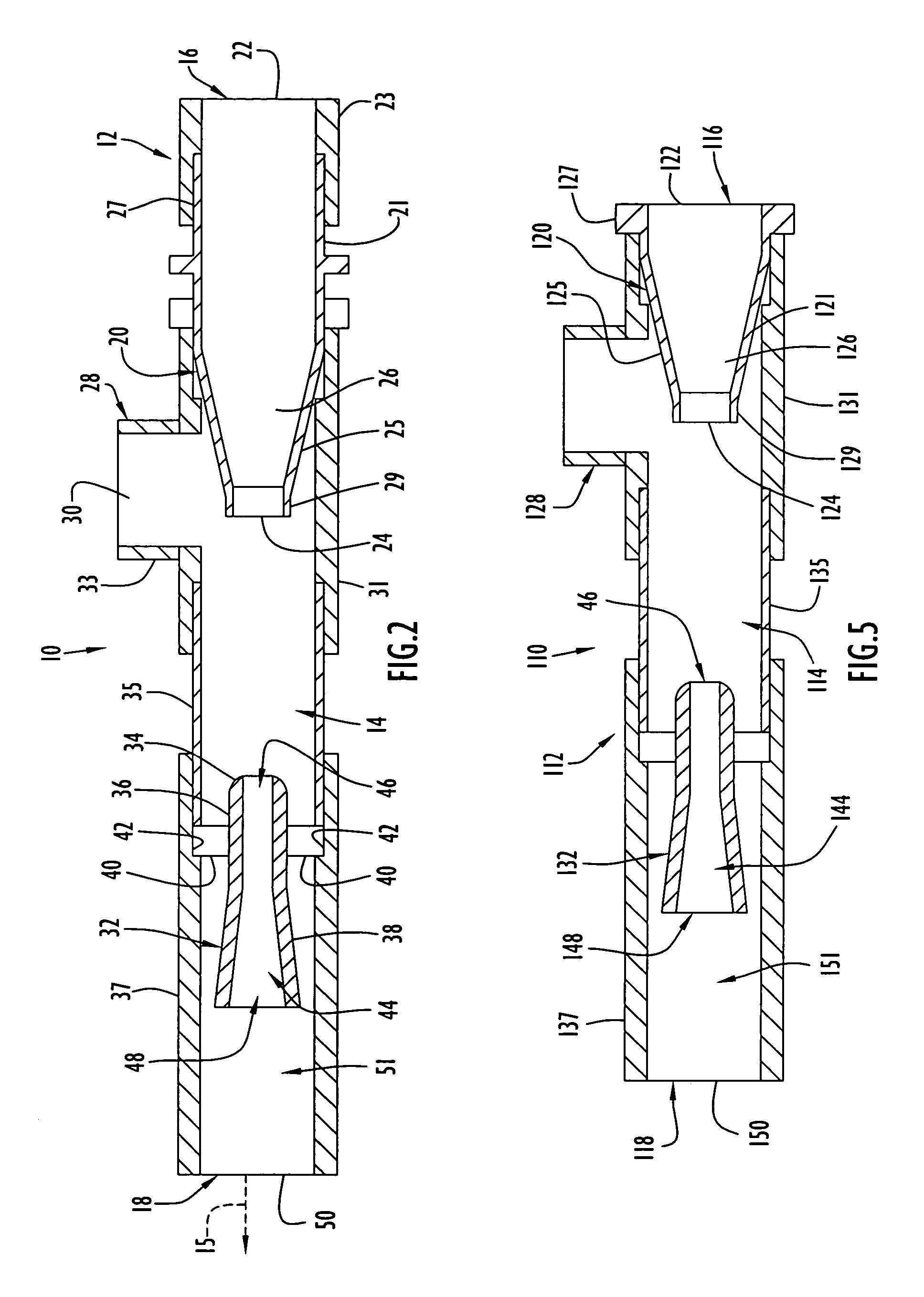
[0021] A fluid ejector pump 10 according to the present invention is illustrated in FIGS. 1 and 2 and comprises an elongate body 12 defining a longitudinally extending flow passage 14 entirely through the body 12. The flow passage 14 has a central longitudinal axis 15. The body 12 and flow passage 14 include an open inlet or downstream end 16 for being supplied with a source of pressurized fluid, such as water, and an open outlet or upstream end 18, opposite the inlet end, through which the fluid is discharged. The wall of body 12 defining flow passage 14 may be formed integrally, unitarily as a single structural part or as a plurality of structural parts connected or assembled in any suitable manner preventing leakage. The inlet end 16 includes a Venturi tube inlet 20 defining a Venturi flow channel therethrough forming a portion of the flow passage 14. The Venturi tube inlet 20 has an entry opening 22 for being supplied with the pressurized fluid, and the Venturi tube inlet extend...


PUM


Abstract

A fluid ejector pump is characterized by a longitudinally extending flow passage with a fluid inlet end and a fluid outlet end. The fluid inlet end includes a Venturi tube inlet having a relatively larger diameter entry opening for being supplied with pressurized fluid and a relatively smaller diameter exit opening within the flow passage. An air inlet communicates with the flow passage adjacent the exit opening for the intake of air into the fluid exiting the Venturi tube inlet. A shaped deflector is located in the flow passage upstream of the exit opening, with the flow passage defining an annular gap around and along the deflector. An upstream end of the deflector has an upward angle causing acceleration of the fluid flowing upstream in the flow passage. A hi-low mixing effect is produced in the flow passage for greater mixing and turbulence of the fluid while vacuum or suction at the suction inlet is increased.

Description

CROSS-REFERENCE TO RELATED PATENT APPLICATION [0001] This application claims priority from prior provisional patent application Ser. No. 60 / 469,355 filed May 9, 2003, the entire disclosure of which is incorporated herein by reference.BACKGROUND OF THE INVENTION [0002] 1. Field of the Invention [0003] The present invention relates generally to fluid pumps and, more particularly, to fluid ejector pumps having a flow passage containing a shaped deflector causing turbulent mixing of fluid flowing through the flow passage. [0004] 2. Brief Discussion of the Related Art [0005] Fluid pumps in which air is mixed with water have been proposed. Such pumps sometimes employ deflectors within flow passages of the pumps to create alterations in fluid flow through the flow passages as represented by U.S. Pat. No. 121,376 to Jamison, Jr., U.S. Pat. No. 524,268 to Walten et al, U.S. Pat. No. 1,810,131 to Daily, U.S. Pat. No. 2,011,224 to Kobiolke et al, U.S. Pat. No. 2,234,631 to Göhre, U.S. Pat. Nos...

Claims


Application Information

Patent Timeline
IPC IPC(8): A62C31/02B01F5/04F04F5/04F04F5/44F04F5/46
CPCA62C31/02B01F5/0413F04F5/463F04F5/04F04F5/44B01F5/0428B01F25/31242B01F25/312
Inventor SOLOMON, JASON D.
Owner SOLOMON JASON D
Why Eureka
Try Eureka