Insertion devices and method of use

a technology of insertion device and axis, which is applied in the direction of osteosynthesis device, internal osteosynthesis, prosthesis, etc., can solve the problems of undesirable balloon balloon inflation about the cannula's axis, and achieve the effects of optimizing the ability of the bone to withstand compressive forces, enhancing bone healing, and minimizing disruption of healthy cancellous and/or cortical bon

a technology of insertion device and axis, which is applied in the direction of osteosynthesis device, internal osteosynthesis, prosthesis, etc., can solve the problems of undesirable balloon balloon inflation about the cannula's axis, and achieve the effects of optimizing the ability of the bone to withstand compressive forces, enhancing bone healing, and minimizing disruption of healthy cancellous and/or cortical bon

US20050090852A1Inactive Publication Date: 2005-04-28ORTHOPHOENIX

Image

  • Insertion devices and method of use
  • Insertion devices and method of use
  • Insertion devices and method of use

Examples


Embodiment Construction

[0086] The present invention overcomes the problems and disadvantages associated with current strategies and designs in insertion devices for use with expandable structures, such as medical balloons. In particular, the present invention provides insertion devices which may be used with expandable structures to direct expansion of the structure as well as to assist in insertion and removal of expandable structures from an interior region of a human or animal body. The methods and instruments suitable for such treatment are more fully described in U.S. Pat. Nos. 4,969,888, 5,108,404, 5,827,289, 5,972,015, 6,048,346 and 6,066,154, each of which are incorporated herein by reference.

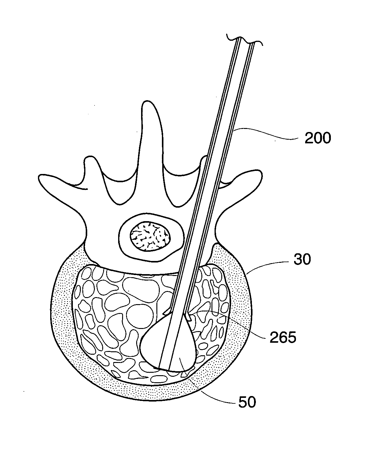
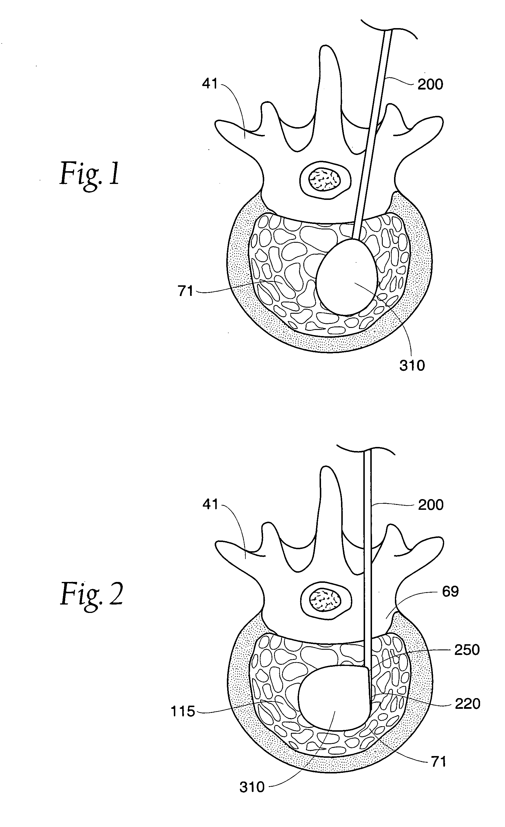
[0087]FIG. 1 depicts a vertebra 41 to be treated using an expandable structure 310. An insertion device 200, such as a cannula or spinal needle, extends through the cortical bone 69 of the vertebra 41, and into the cancellous bone 71. An expandable structure 310 is introduced into the vertebra 41 through the...


PUM

PropertyMeasurementUnit
thicknessaaaaaaaaaa
diameteraaaaaaaaaa
fracture areaaaaaaaaaaa

Abstract

This invention relates to devices for inserting expandable structures, such as medical balloons, into interior regions of a human or animal body, as well as methods for their use. The insertion devices described herein are capable of directionally guiding and / or inhibiting expansion of an expandable structure within an interior region of an animal or human body to create optimally placed cavities for repair, augmentation and / or treatment of fractured and / or diseased bone.

Description

RELATED APPLICATIONS [0001] This application is a continuation-in-part of co-pending U.S. application Ser. No. 09 / 828,470, filed Apr. 6, 2001, entitled “Insertion Devices and Method of Use,” which claims the benefit of provisional U.S. Application Ser. No. 60 / 195,207, filed Apr. 7, 2000. FIELD OF THE INVENTION [0002] This invention relates to an insertion device which is capable of guiding expansion of an expandable structure towards or away from a desired direction and / or interior region of an animal or human body. This invention further relates to an insertion device for inserting expandable structures, such as medical balloons, into an interior region of a human or animal body, wherein the device is capable of expanding at the tip. The present invention also relates to methods of using the disclosed devices in the repair, augmentation and / or treatment of fractured and / or diseased bone. BACKGROUND OF THE INVENTION [0003] Expandable structures, such as balloon dissectors and cathet...

Claims


Application Information

Patent Timeline
28 Apr 2005
Publication
US20050090852A1
IPC
A61B17/00; A61B17/32; A61B17/34; A61B17/68; A61B17/88; A61B17/56; A61F2/00; A61F2/44; A61F2/46; A61F2/958
CPC
A61B17/3417; A61F2310/00353; A61B17/3468; A61B17/3472; A61B17/68; A61B17/8805; A61B17/8855; A61B17/8858
Inventors
LAYNE, RICHARD W.; SETO, CHRISTINE L.