
Automatic portable door operating system

a portable door and operating system technology, applied in the direction of wing operation mechanisms, door/window fittings, constructions, etc., can solve the problems of limiting the application of such improved door openers to entrance doors and automated doors, and the addition of the cost of such units,

Inactive Publication Date: 2005-05-05
4378580 CANADA
View PDF38 Cites 77 Cited by
  • Summary
  • Abstract
  • Description
  • Claims
  • Application Information

AI Technical Summary

Benefits of technology

[0014] One object of the present invention is to provide a portable and inexpensive apparatus for controlling the operation for a swing type door.

Problems solved by technology

The additional expense associated with the manufacture and operation of such units is relatively high.
As an example, when a clutch or other disengagement mechanism is required for operation, the resulting system can become too expensive, especially for widespread use.
This limits the applications for such improved door openers to entrance doors and automated doors for handicapped people leaving the market of fast food restaurants and hygienic applications unattended.
Most door operating systems do not possess any features that would suspend the door opening if any obstacle in its way is encountered.
The systems which do have such features, such as that which is described in a U.S. Pat. No. 6,002,217 are complex and unreliable due to the fact that door inertia and dynamic loads during the door operation can be easily misrepresented by a controller as an overload condition, which creates a pattern of malfunction.
Another issue with the known door operating systems is bulkiness and that they occupy most of the width and considerable height of the swing door upper frame.
This creates an unappealing addition to the interior of the office, house or washroom.
The high price of such devices stems from the complexity of the design itself and creates a challenging barrier for penetration to such powerful and potent markets as highly frequented public areas.
Although a multitude of swinging door automatic openers are available in the marketplace, particularly for disabled function applications, these are quite sophisticated and elaborate, however their purchase and installation costs make them prohibitive for a sanitary application such as it is envisaged with the instant technology.
As a general rule, most door operating systems are-not capable of functioning during power blackouts.
Since most automatic door operating system can naturally be situated in public facilities such as hospitals, offices, restaurants, etc., the loss of power paralyzes these devices.

Method used


Image

  • Automatic portable door operating system
  • Automatic portable door operating system
  • Automatic portable door operating system

Examples


Embodiment Construction

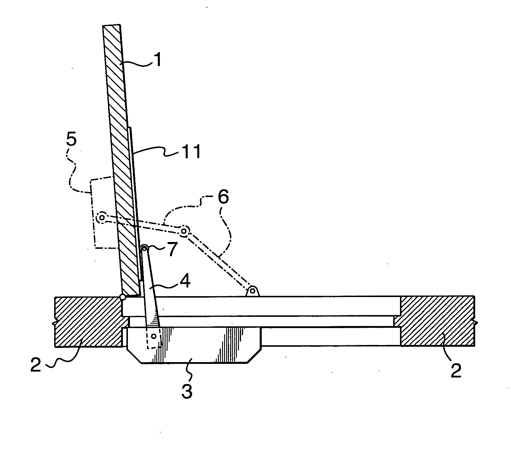
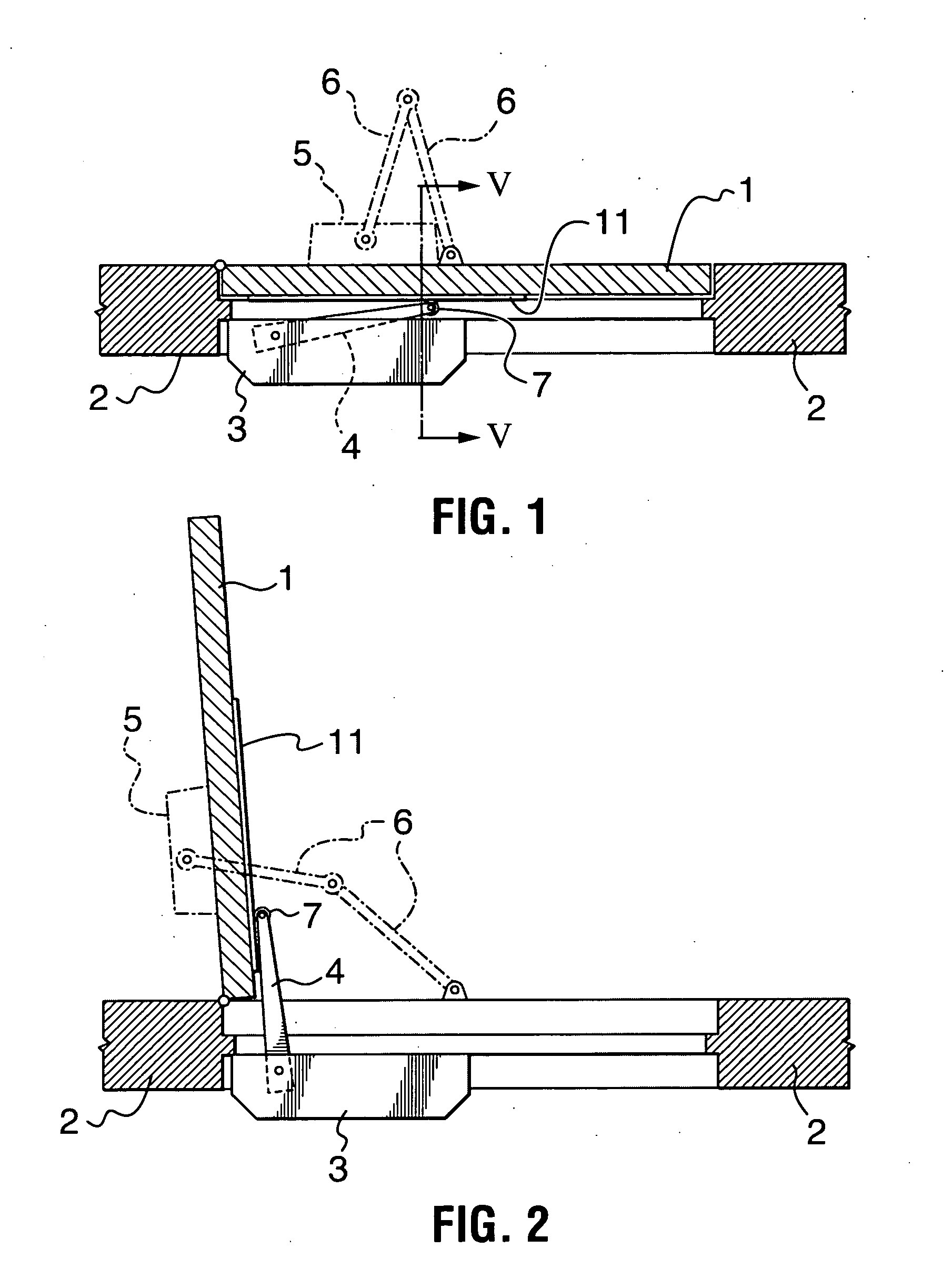
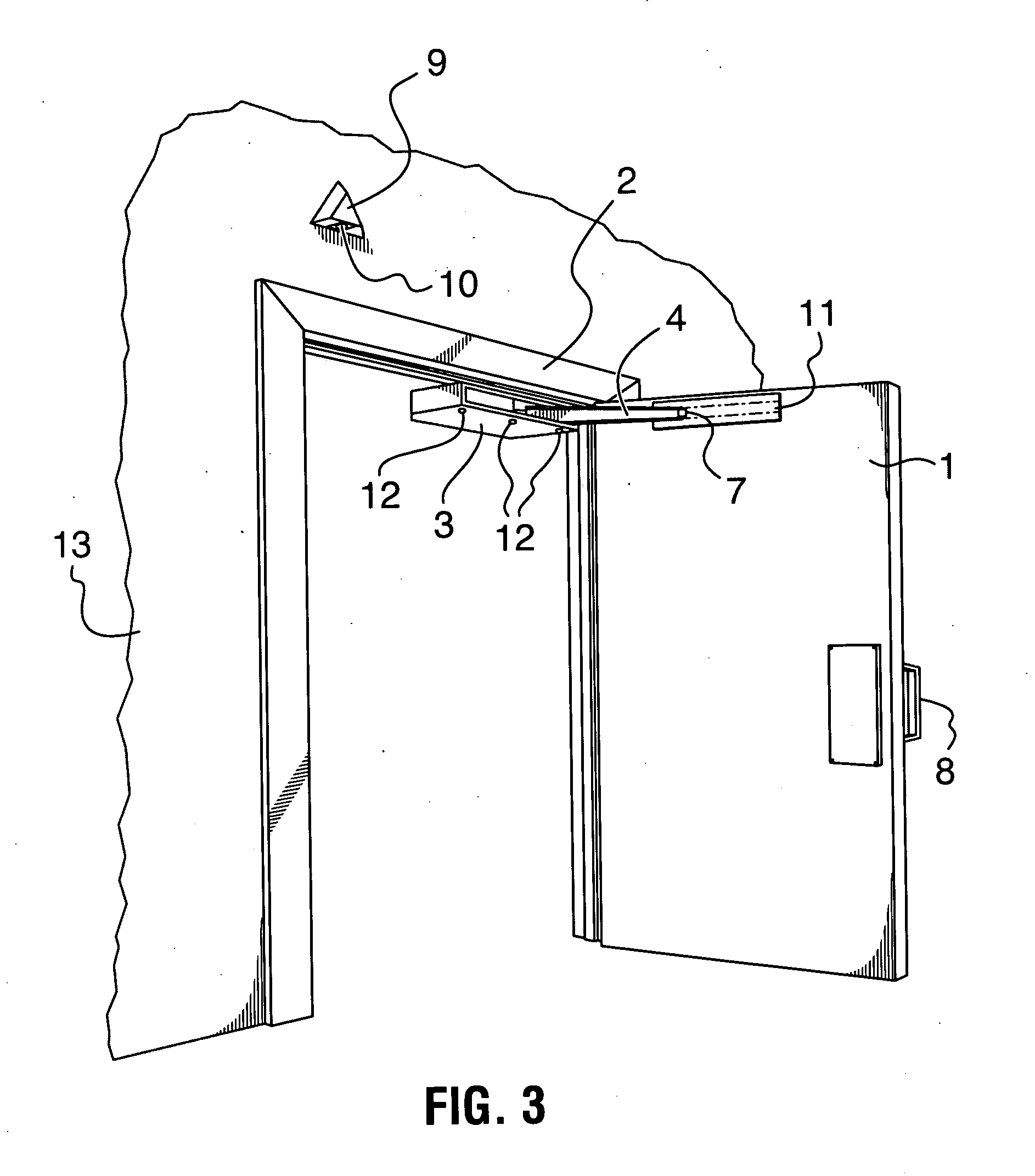
[0052] Referring now to FIGS. 1 through 3 and 5 there are shown a swing door 1 with hinges on its left side, frame 2 accommodating such door 1, door opener 3 attached to the upper portion of the frame 2 by means of three screws 12 (FIG. 3). The door opener 3 has an arm 4 pivotally connected to its housing and having a roller 7 at its free end. Alternatively, the door can contain a door closer spring consisting of the housing 5 with linked arms 6.

[0053] When swung, the arm 4 pushes the door 1 through the pilot plate (strike plate) 11. When the arm 4 is retracted, the door is closed either by the action of the door closer or by the arm 4, which can have a link with the door 1 through the pilot plate 11 or by other means. The invention in one of its practical variants has a Passive Infra Red (PIR) detector 9 attached to the wall 13 with lens 10 facing the area near the handle 8 of the door 1 (when the door is in closed position). One of the possible variants of such detector is a PARA...


PUM


Abstract

The present invention relates to a door operating system for controlling the movement of a door, more particularly to “no touch” door openers for public washrooms and households. The system has a motor with a gear chain where the high gear is generally semicircularly shaped engaged with a swinging arm coupled with the door through the roller and a pilot plate. The unit is activated upon receipt of the signal from overhead passive infrared or hand proximity detecting sensors and has a controlling system to provide for opening and closing the door, as well as retraction of the arm in the event of door encountering an obstacle or in an overload condition of the motor. The arm and a gear are linked pivotally with each other and with the unit housing. They are coupled through a spring suspension system and have a clutch mechanism preventing overloading. The only external moving part is the arm, which is, along with geared sector, protected by a flexible member providing security to prevent accidental jamming of objects by it. The unit may be battery operated with a low voltage and low power AC / DC switching wall adapter. In autonomous operation it can provide up to 700 opening cycles without external power.

Description

CROSS-REFERENCE TO RELATED APPLICATIONS [0001] This application claims benefit of U.S. Provisional Application No. 60 / 499,348, filed Sep. 3, 2003.FIELD OF THE INVENTION [0002] The present invention relates to an apparatus and method for controlling the operation of a door, and, more particularly, the present invention relates to devices for automatic opening or / and closing of swing type doors. BACKGROUND OF THE INVENTION [0003] Hydraulic and pneumatic door controlling devices for swing doors are well known (U.S. Pat. Nos. 4,793,023, 4,414,703 and 4,378,612.). Hydraulic and pneumatically operated openers, or opening assist mechanisms are also known from the prior art as exemplified in U.S. Pat. Nos. 3,948,000, 3,936,977, 4,955,194, and 4,429,490. Further, electromechanical automatic door openers are known, for example, from U.S. Pat. Nos. 2,910,290, 3,127,160, 4,045,914 and 4,220,051. Each type of these door openers has its own advantages and disadvantages. [0004] There are also comb...

Claims


Application Information

Patent Timeline
Patent Type & Authority Applications(United States)
IPC IPC(8): E05F3/22E05F15/00E05F15/12E05F15/20
CPCE05F3/22E05F15/74E05Y2400/614E05Y2400/86E05Y2900/112E05F15/00E05Y2201/236E05Y2400/53E05Y2201/47E05Y2600/13E05Y2800/246E05Y2800/252E05F3/227E05F15/40E05F15/41E05F15/619E05F15/622E05F15/624E05F15/63E05Y2201/214E05Y2900/132
Inventor OKULOV, PAUL D.ZOUAK, AMIR
Owner 4378580 CANADA
Learn More