Crane trolley with low overall height

a trolley and overall height technology, applied in the field of crane trolleys, can solve the problems of occupying additional space, slipping, and running wheels arranged on the rails, and achieve the effect of simple construction and reliable reduction of the slippage of the driven running wheel

Active Publication Date: 2005-05-05
KONECRANES GLOBAL
View PDF8 Cites 33 Cited by
  • Summary
  • Abstract
  • Description
  • Claims
  • Application Information

AI Technical Summary

Benefits of technology

[0008] The invention provides a crane trolley of the aforementioned kind, which ensures a

Problems solved by technology

Due to this off-center shifting of the center of gravity, there is a risk when operating without a payload that the running wheels arranged on the rail, especially the lower flange of a beam, will lift up relative to the hoisting mechanism.
A counterweight, on the one hand, takes up additional space, and on the other hand the proper weight of the crane trolley and the load on the beam is nee

Method used


Image

  • Crane trolley with low overall height
  • Crane trolley with low overall height
  • Crane trolley with low overall height

Examples


first embodiment

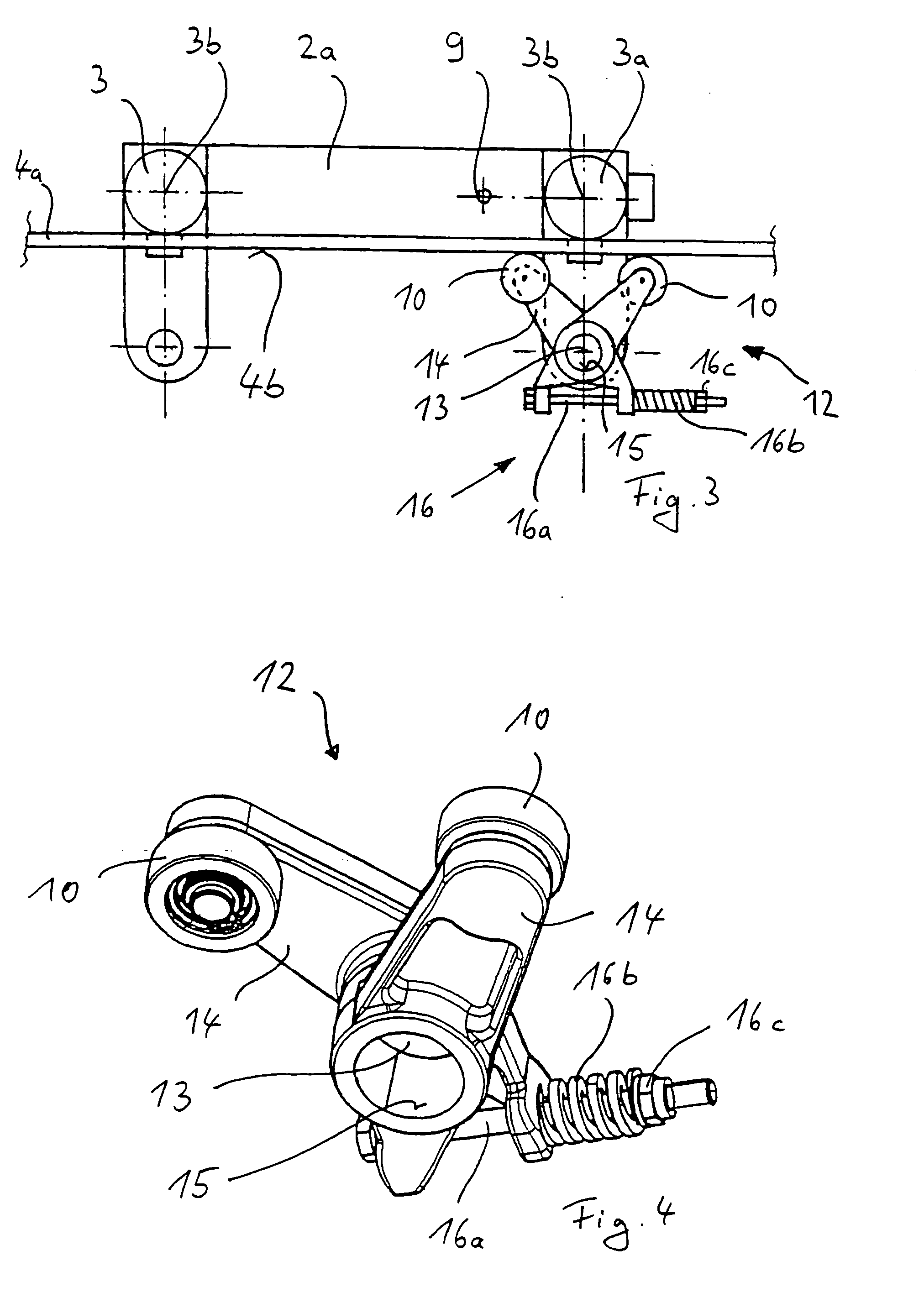
[0037]FIGS. 5 and 6 show two variants of how the support rod linkage 12 can be positioned exactly underneath the driven running wheel 4a on the cross arm 8. In the first embodiment shown in FIG. 5, the positioning of the linkage 12 occurs by a spacer tube 17 which can be placed on the cross arm 8, thrusting against the frame piece 2a at one end and against the levers 14 of the linkage 12 at the other end.

second embodiment

[0038] depicted in FIG. 6, the support rod linkage 12 is positioned by a set collar 18 that can be placed on the cross arm 8 and bears against the linkage 12, and the set collar 18 can be locked on the cross arm 8 by a threaded pin 18a, for example, or a stud screw 18a.

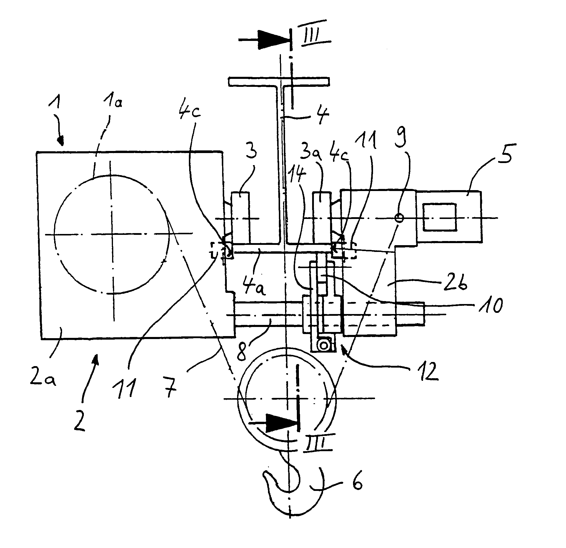
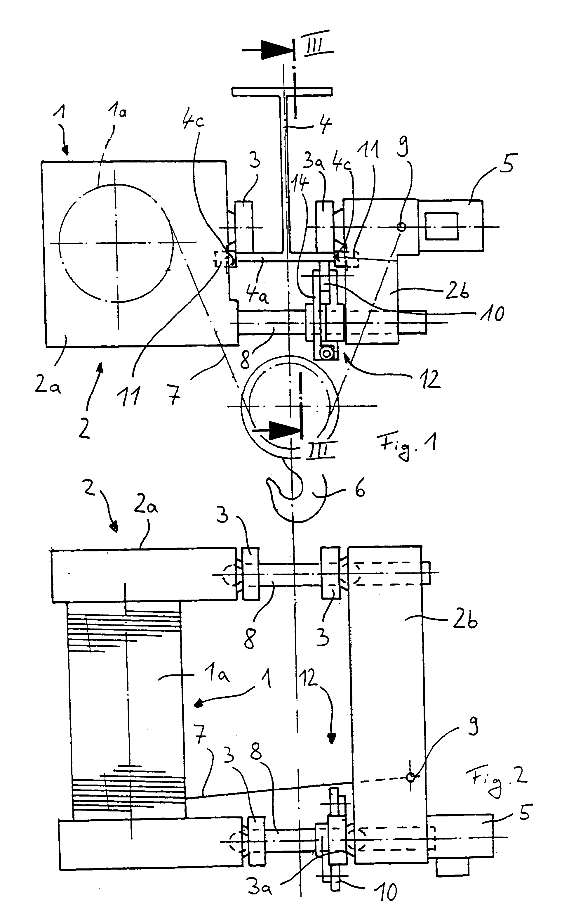
[0039] With the help of the spacer tube 17 or the set collar 18, the position of the support rod linkage 12 can be chosen freely according to the width B of the lower flange 4a of the beam 4, but it will preferably be adjusted so that the friction rollers 10 are arranged centrally beneath the driven running wheel 3a.

[0040] Besides using only one pair of friction rollers that is arranged exclusively beneath the driven running wheel 3a, it is also possible, of course, to arrange pairs of friction rollers beneath several running wheels 3, especially beneath all running wheels 3 on the part of the lower flange 4a of the beam 4 that lies opposite the frame piece 2a containing the hoisting mechanism 1, since these runnin...


PUM


Abstract

A crane trolley, especially a single-rail trolley with a short overall height, with a traveling mechanism frame (2) having a hoisting mechanism (1), which can travel by running wheels (3, 3a) on a rail, especially a lower flange (4a) of an essentially horizontal beam (4), wherein at least one running wheel (3a) can be driven, and a friction roller (10) interacting with the driven running wheel (3a) is arranged on the underside (4b) of the rail. In order to create a crane trolley that guarantees a reliable reduction in the slippage of the driven running wheel (3a) with a simple design, a pair of friction rollers (10) is provided, which may be positioned against the underside (4b) of the rail by adjusting the spacing from each other via a common pressing mechanism.

Description

BACKGROUND OF THE INVENTION [0001] The invention concerns a crane trolley, particularly one with a short overall height. The invention is particularly useful with a single-rail trolley having a running gear frame having a hoisting mechanism, which can travel by running wheels on a rail. The invention is illustrated with a crane trolley having a lower flange of an essentially horizontally situated beam, with at least one running wheel being driven, and on the underside of the rail is arranged a friction roller interacting with the driven running wheel. [0002] In crane trolleys with short overall height, in order to accomplish a compact and space-saving construction, the hoisting mechanism is arranged at the side, next to the beam carrying the rail, so that the actual load lifting tackle—the load hook—can be lifted as high as possible underneath the beam. This arrangement of the hoisting mechanism next to the beam produces an off-center position of the center of gravity of the running...

Claims


Application Information

Patent Timeline
IPC IPC(8): B66C9/14B66C11/06
CPCB66C11/06B66C9/14
Inventor WINTER, KLAUS-JURGENDAMMER, MICHAELFLAIG, HEINRICHAPPEL, ERIK
Owner KONECRANES GLOBAL
Why Eureka
Try Eureka