Cooling fan and cooling fan module

Pending Publication Date: 2022-10-06
BROSE FAHRZEUGTEILE SE & CO KGAA WUERZBURG
View PDF0 Cites 1 Cited by
  • Summary
  • Abstract
  • Description
  • Claims
  • Application Information

AI Technical Summary

Problems solved by technology

Since excessive temperatures would damage the internal combustion engine, for example by removing a lubricating film, by burning inlet valves and/or outlet valves for the fuel-air mixture or the like, the internal combustion engine has to be actively cooled.
In the case of electrically driven or drivable motor vehicles, however, the additional problem occurs that the battery starts to degenerate at a high battery temperature, for example higher than 45° C. This means that, with such high temperatures, electrochemical reactions occur inside the battery which damage or completely destroy the battery.
Relatively high currents are present in the course of such fast charging, which as a result bring about an incre

Method used


Image

  • Cooling fan and cooling fan module
  • Cooling fan and cooling fan module
  • Cooling fan and cooling fan module

Examples


Embodiment Construction

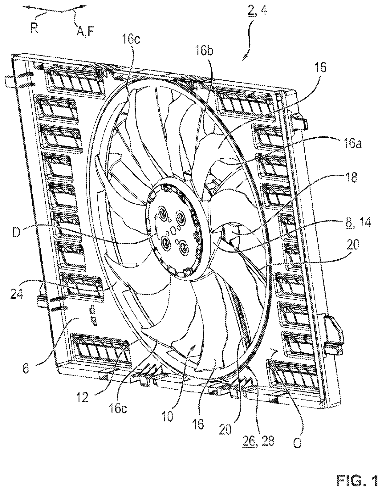
[0061]Referring now to the figures of the drawing in detail and first, in particular, to FIG. 1 thereof, there is shown a perspective view of a cooling fan module 2 with a cooling fan 4. The cooling fan 4 has a fan shroud 6 and a fan wheel 8.

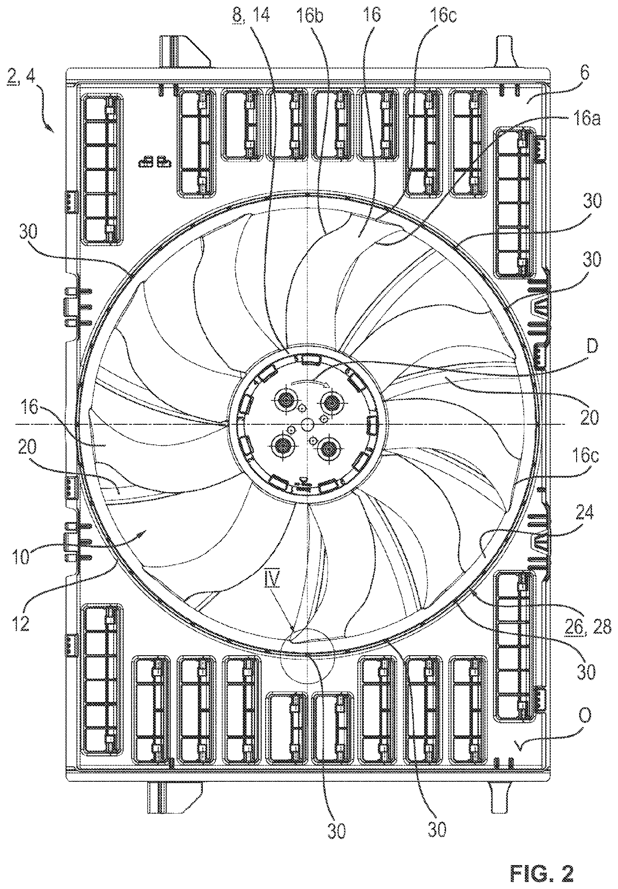
[0062]A fan wheel recess 10, which is to be defined or is defined by a shroud ring 12, is configured in the fan shroud 6. The fan wheel 8 has a central hub cup 14, a number of blades 16 (fan vanes) which are oriented in the radial direction R being integrally formed on the outer face thereof. As is visible in particular in FIG. 2, the fan wheel 8 in this exemplary embodiment has nine blades 16. The blades 16 are provided with reference numerals merely by way of example in the figures.

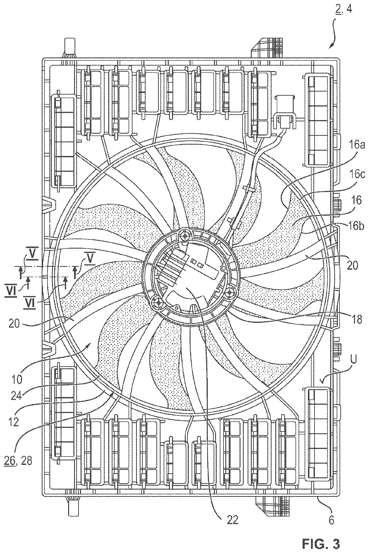
[0063]A motor holder or holder 18 coupled to the hub cup 14 is centrally arranged inside the fan wheel recess 10 and mechanically connected via struts 20 to the fan shroud 6. As is visible in particular in FIG. 3, the motor holder 18 in this case is held by means of...


PUM


Abstract

A cooling fan has a fan shroud with a fan wheel recess surrounded by a shroud ring and a fan wheel rotatably mounted in the fan wheel recess for conveying the air flow along a conveying direction from a shroud upper side to a shroud underside. The fan wheel has a central hub cup with radially orientated blades and an outer ring connecting the blades at the blade tip ends. A circumferential ring gap is formed between the outer ring and the shroud ring. A rib structure in the ring gap reduces swirl in a gap flow orientated against the conveying direction. A shroud ring section of the shroud ring extends axially beyond the outer ring on the shroud underside. The shroud ring section is orientated parallel or at an angle of inclination and radially inwards relative to the conveying direction.

Description

CROSS-REFERENCE TO RELATED APPLICATION[0001]This application is a continuation, under 35 U.S.C. § 120, of copending International Patent Application PCT / EP2020 / 086221, filed Dec. 15, 2020, which designated the United States; this application also claims the priority, under 35 U.S.C. § 119, of German Patent Application DE 10 2019 220 232.2, filed Dec. 19, 2019; the prior applications are herewith incorporated by reference in their entirety.FIELD AND BACKGROUND OF THE INVENTION[0002]The invention relates to a cooling fan, which is preferably electrically (electromotively) driven and which is particularly suited for a motor vehicle. The cooling fan comprises a fan shroud having a fan wheel recess and having a fan wheel comprising an outer ring (casing ring) which is rotatably arranged or positioned in the fan wheel recess. The invention further relates to a cooling fan module, in particular as a preassembled structural unit.[0003]Modern internal combustion engines, in particular four-s...

Claims


Application Information

Patent Timeline
IPC IPC(8): F04D29/52F04D25/06F04D29/32F01P5/06
CPCF04D29/522F04D25/06F04D29/325F01P5/06F01P2005/046F01P11/10F04D29/164F04D29/326F04D29/663F04D29/526
Inventor FROH, CHRISTIANMAURER, BERNDDREESEN, THOMAS
Owner BROSE FAHRZEUGTEILE SE & CO KGAA WUERZBURG
Why Eureka
Try Eureka