Impact load reduction structure

Active Publication Date: 2017-03-30
SUBARU CORP
View PDF11 Cites 4 Cited by
  • Summary
  • Abstract
  • Description
  • Claims
  • Application Information

AI Technical Summary

Benefits of technology

[0008]It is desirable to provide an impact load reduction structu

Problems solved by technology

Batteries installed in electrically-powered vehicles, such as electric vehicles and hybrid vehicles, require large capacity and have large weight.
Thus, when the front section of the electri

Method used


Image

  • Impact load reduction structure
  • Impact load reduction structure
  • Impact load reduction structure

Examples


Embodiment Construction

[0023]An example of the present invention will be described below with reference to the appended drawings.

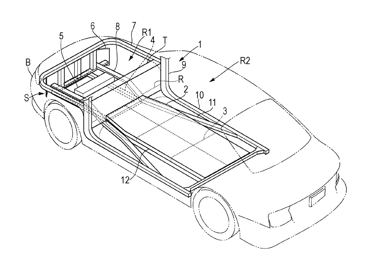
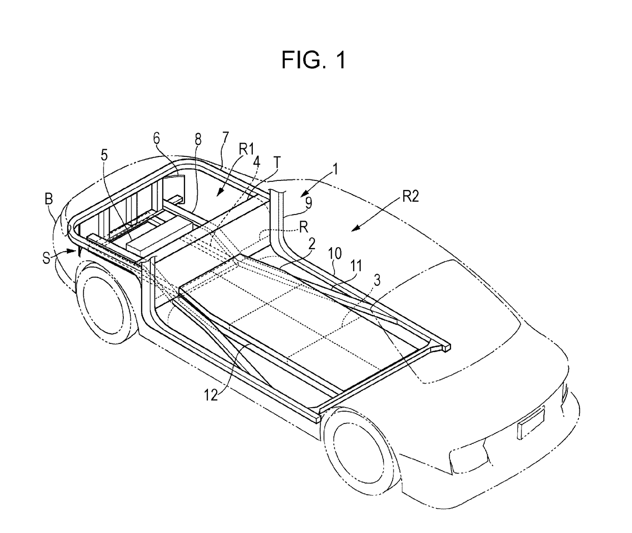
[0024]FIG. 1 illustrates the configuration of an electric vehicle equipped with an impact load reduction structure according to an example of the present invention. This electric vehicle has a vehicle body frame 1 that supports a vehicle body, a battery housing 2 fixed to the vehicle body frame 1, a plurality of batteries 3 disposed within the battery housing 2, a sub frame 4 disposed on the front side of the battery housing 2, and a driving unit 5 electrically coupled to the plurality of batteries 3 via wires (not illustrated).

[0025]The vehicle body frame 1 has a bumper frame 6, a pair of front upper frames 7, a pair of front side frames 8, a pair of front pillars 9, a pair of side sills 10, and a pair of floor side frames 11.

[0026]The bumper frame 6 is disposed at the front section of the electric vehicle and supports a bumper B. The bumper frame 6 extends in a curved manner i...


PUM


Abstract

An impact load reduction structure includes a battery frame and a load reduction frame. The battery frame is fixed to a vehicle body frame of an electrically-powered vehicle and supports a battery. The load reduction frame is disposed so as to extend in a front-rear direction on a front side of the battery frame. A rear section of the load reduction frame is disposed facing a front section of the battery frame with a predetermined gap therebetween such that the load reduction frame comes into contact with the battery frame when the electrically-powered vehicle is involved in a collision.

Description

CROSS-REFERENCE TO RELATED APPLICATIONS[0001]The present application claims priority from Japanese Patent Application No. 2015-193461 filed on Sep. 30, 2015, the entire contents of which are hereby incorporated by reference.BACKGROUND[0002]1. Technical Field[0003]The present invention relates to impact load reduction structures, and particularly, to an impact load reduction structure that reduces an impact load transmitted to a battery for driving an electrically-powered vehicle.[0004]2. Related Art[0005]Batteries installed in electrically-powered vehicles, such as electric vehicles and hybrid vehicles, require large capacity and have large weight. Therefore, an electrically-powered vehicle is normally provided with a battery frame for supporting a battery. For instance, the battery frame is provided in a large space under the floor of the vehicle cabin, and a plurality of batteries are collectively disposed within the battery frame. There is a demand for a technology for suppressin...

Claims


Application Information

Patent Timeline
IPC IPC(8): B62D21/15B60K1/04
CPCB62D21/155B60K2001/0438B60K1/04B60Y2306/01B62D25/082B62D25/2018
Inventor TSUKADA, TAKEHISAMATSUDA, HIROSHI
Owner SUBARU CORP
Why Eureka
Try Eureka