Workpiece transfer system and workpiece transfer method

a technology of workpiece transfer and transfer system, which is applied in the direction of ammunition loading, manufacturing tools, hoisting equipment, etc., can solve the problems of heavy physical labor in the transfer operation, and achieve the effects of small output, reduced rotational load on the rotary drive means, and reduced weigh

Inactive Publication Date: 2010-07-27
HONDA MOTOR CO LTD
View PDF4 Cites 3 Cited by
  • Summary
  • Abstract
  • Description
  • Claims
  • Application Information

AI Technical Summary

Benefits of technology

[0015]In accordance with the first aspect of the present invention, since the workpiece can be inclined by operation of the swing drive means and inverted by operation of the rotary drive means, a single worker can easily give the workpiece an inclination and inversion attitude change. Moreover, when the rotary drive means is operated, since the workpiece is inclined in advance by operation of the swing drive means to a predetermined angle restricted by the restricting means to thus make it possible to position the center of gravity of the workpiece on the axis of rotation of the rotary drive means or the vicinity thereof, the rotational load on the rotary drive means can be reduced; it is thereby sufficient for the rotary drive means to be of a small type with a relatively small output, and a reduction in weight and a low production cost can be achieved for the system.
[0016]Furthermore, in accordance with the second aspect of the present invention, by carrying out raising / lowering of the first arm, rotation of the first arm around the axis of the support post, relative pivoting of the first and second arms, rotation of the bracket, and swinging of the workpiece support arm, the workpiece retained by the workpiece retaining means can with little effort be given a change of position, such as raising / lowering, horizontal movement, inclination, or inversion, and it is therefore possible for a single worker to easily transfer the workpiece to a desired location even in a confined place, thereby greatly reducing the load on the worker.
[0017]Moreover, in accordance with the third aspect of the present invention, operation of the first brake can restrict rotation of the first arm around the axis of the support post, operation of the second brake can restrict relative pivoting of the first and second arms, operation of the third brake can restrict rotation of the bracket, and transfer of the workpiece can be carried out more easily and appropriately while stabilizing the attitude thereof.
[0018]Furthermore, in accordance with the fourth aspect of the present invention, rotation of the bracket can be restricted at the same time as operation of the rotary drive means stops, the attitude of the workpiece in an inverted state can be stabilized, and the transfer operation can be carried out more easily and appropriately.
[0019]Moreover, in accordance with the fifth aspect of the present invention, even when an object to which the workpiece is to be transferred is moving, aligning the direction of horizontal movement of the support post with the direction of movement of the object enables the workpiece to be easily transferred to the object.
[0020]Furthermore, in accordance with the sixth aspect of the present invention, when the swing drive means operates, the swing of the workpiece support arm can automatically be restricted to a fixed angle by the restricting means, and it is therefore possible to always appropriately position the center of gravity of the workpiece in the vicinity of the axis of rotation of the rotary drive means, thereby reliably reducing the rotational load on the rotary drive means.

Problems solved by technology

In this case, since the spare wheel is a heavy object, the transfer operation involves heavy physical labor.

Method used


Image

  • Workpiece transfer system and workpiece transfer method
  • Workpiece transfer system and workpiece transfer method
  • Workpiece transfer system and workpiece transfer method

Examples


embodiment 1

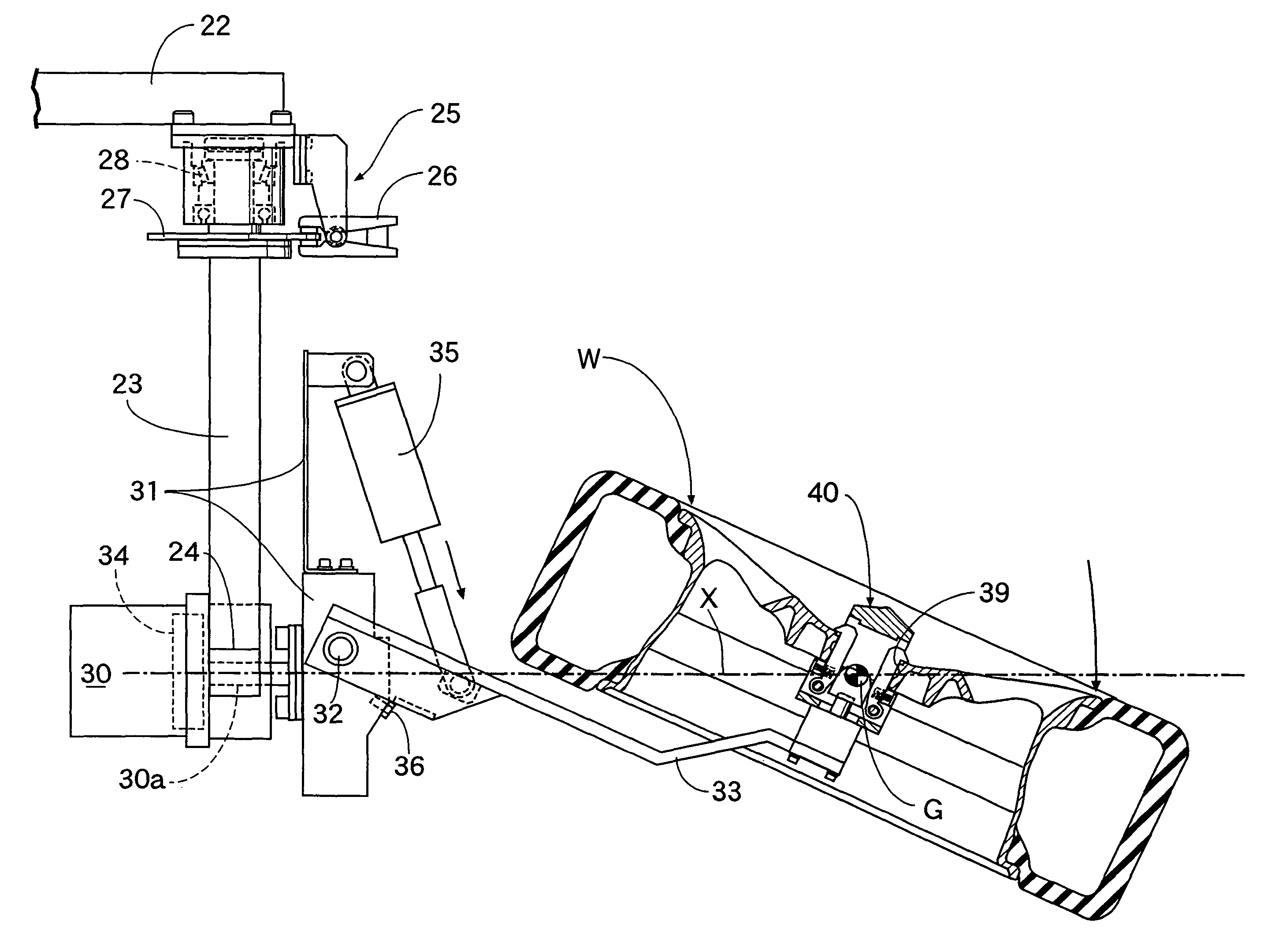
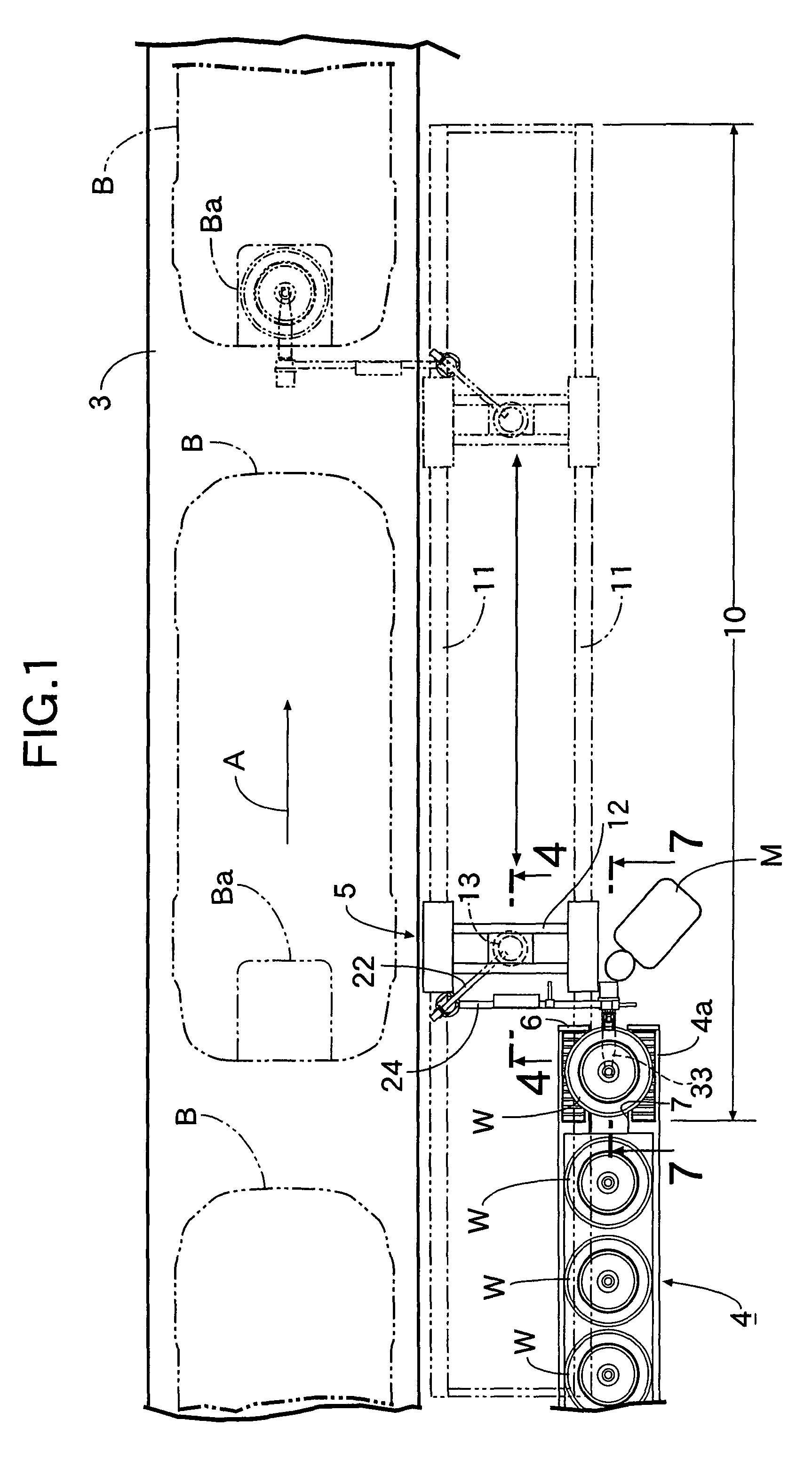
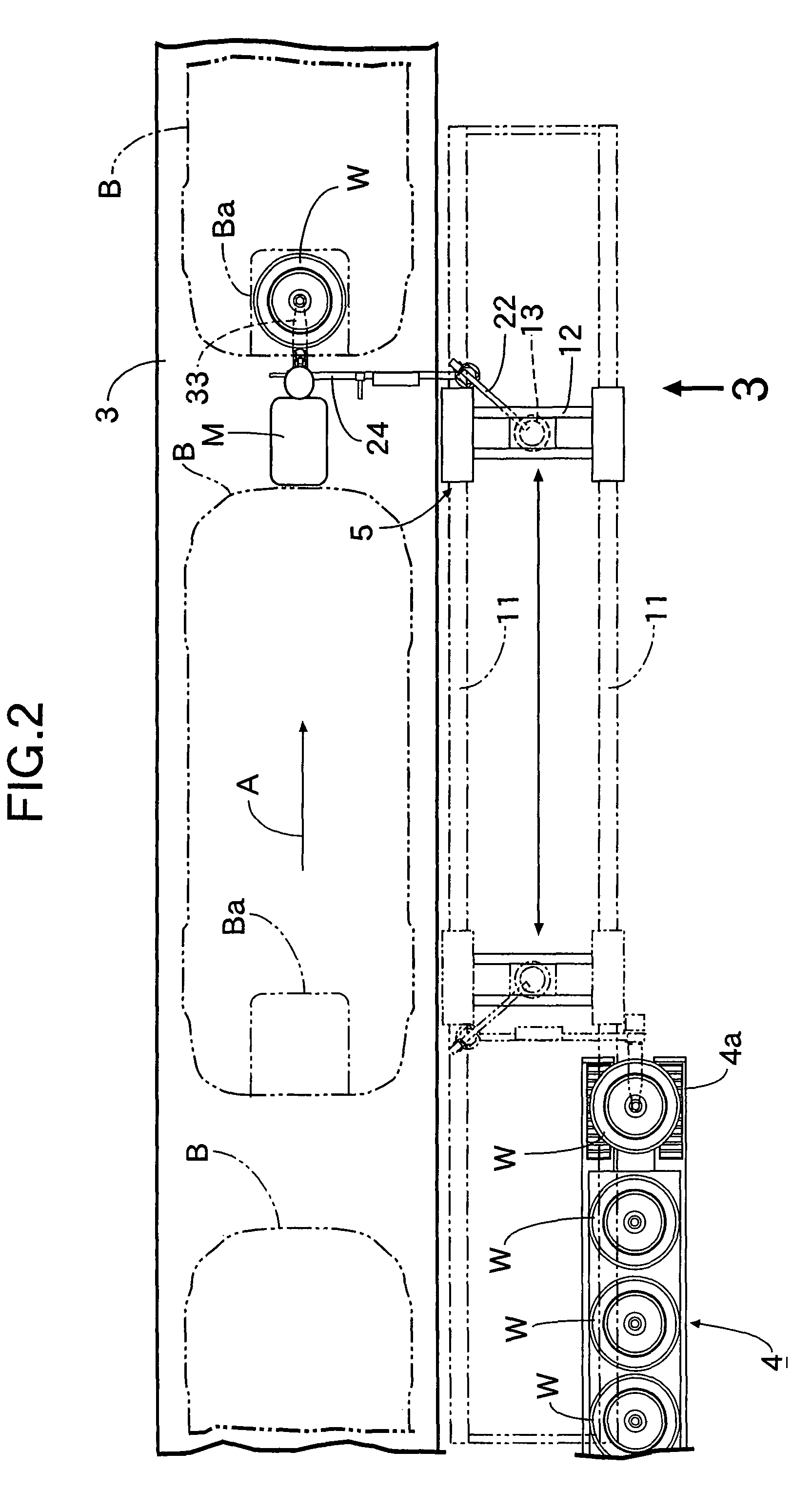
[0051]First, as shown in FIG. 1 to FIG. 3, an assembly line for a motor vehicle is provided with an overhead conveyor 1 for supporting a large number of vehicle bodies B by means of a large number of hangers 2 and transporting them in a fixed direction A, a moving floor 3 traveling in synchronism with movement of the hangers 2, a spare wheel supply conveyor 4 installed on a floor on one side of the moving floor 3, and a workpiece transfer system 5 of the present invention for transferring a spare wheel W that has arrived at a discharge section 4a of the spare wheel supply conveyor 4 to a spare wheel retaining dish Ba in a lower part of each of the vehicle bodies B that are being transported.

[0052]The spare wheel supply conveyor 4 transports the spare wheel W toward the discharge section 4a, the spare wheel W being in a horizontal state with its outer side upward, and the discharge section 4a is provided with a stopper wall 6 for stopping movement of the spare wheel W and a cutout 7 ...


PUM


Abstract

A workpiece transfer system includes a bracket rotatably supported on a support part, a rotary drive mechanism provided on the support part in order to rotate the bracket, a workpiece support arm swingably and axially supported on the bracket, a swing drive mechanism provided on the bracket in order to swing the workpiece support arm, and a workpiece retainer provided on a tip end part of the workpiece support arm and retaining a workpiece that is to be transferred, the workpiece being inclined by operation of the swing drive mechanism when the rotary drive mechanism is operated so that a center of gravity of the workpiece comes on the vicinity of an axis of rotation of the rotary drive mechanism. This reduces the rotational load on the rotary drive mechanism, and since a small size and a reduction in weight can be achieved for the system, the workpiece transfer system and method enables a single worker to easily give a workpiece an inclination and inversion attitude change.

Description

CROSS-REFERENCE TO RELATED APPLICATIONS[0001]The present application is a U.S. National phase of, and claims priority based on PCT / JP2005 / 022924 filed 14 Dec. 2005, which, in turn, claims priority from Japanese patent application 2004-364359, filed 16 Dec. 2004. The entire disclosure of each of the referenced priority documents is incorporated herein by reference.TECHNICAL FIELD[0002]The present invention relates to a workpiece transfer system and a workpiece transfer method that, when transferring a workpiece to a predetermined location, can give the workpiece an inclination and inversion attitude change.BACKGROUND ART[0003]For example, in an assembly line for a motor vehicle, when a spare wheel is taken out of a spare wheel supply section and transferred to a spare wheel retaining dish in a lower rear part of the motor vehicle, it is necessary to give the spare wheel various attitudes such as inclining it and inverting it, and all such operations have conventionally been carried o...

Claims


Application Information

Patent Timeline
Patent Type & Authority Patents(United States)
IPC IPC(8): B66C23/00
CPCB62D65/12B66C23/18Y10S212/901
Inventor UEDA, MINORUMITSUHASHI, MASAMIMASHINO, NOBUOANDOU, EISAKUTOKOYO, YASUSHI
Owner HONDA MOTOR CO LTD
Why Eureka
Try Eureka