Fan unit air flow control

a technology of air flow control and fan unit, which is applied in the direction of process and machine control, liquid fuel engine, instruments, etc., can solve the problems of exacerbated noise problem in clean room facilities, inability to reduce noise to a satisfactory level, and excessive so as to reduce the noise of the fan unit and reduce the turbulence

Inactive Publication Date: 2005-05-05
KYODO ALLIED IND LTD
View PDF8 Cites 27 Cited by
  • Summary
  • Abstract
  • Description
  • Claims
  • Application Information

AI Technical Summary

Benefits of technology

[0010] The air flow channel creating a constriction on air flow to raise air pressure within the air flow channel to thereby create substantially mono-directional air flow in the air flow channel and through the outlet opening, with reduced turbulence such that noise from said fan unit is minimised.

Problems solved by technology

However, such powerful fan units create excessive noise.
However, such an elementary method often does not reduce the noise to a satisfactory level for workers inside the clean room facility.
The problem associated with the noise in a clean room facility is exacerbated in a confined space or enclosures such as, for example, a multi-storey wafer fabrication plant.
Where there is low height clearance, the noise from fan units may be quite pronounced.

Method used


Image

  • Fan unit air flow control
  • Fan unit air flow control
  • Fan unit air flow control

Examples


Embodiment Construction

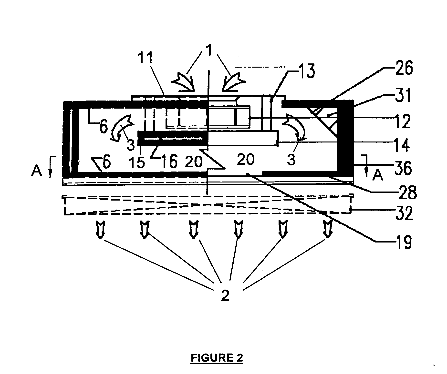
[0028] In the following description, numerous specific details are set forth such as, for example, guides and baffles, in order to-provide a thorough understanding of the invention. In other instances, well-known components such as, for example, the motors for the fan blower and ducts connected to the fan units, are not shown and / or described in order not to obscure the invention.

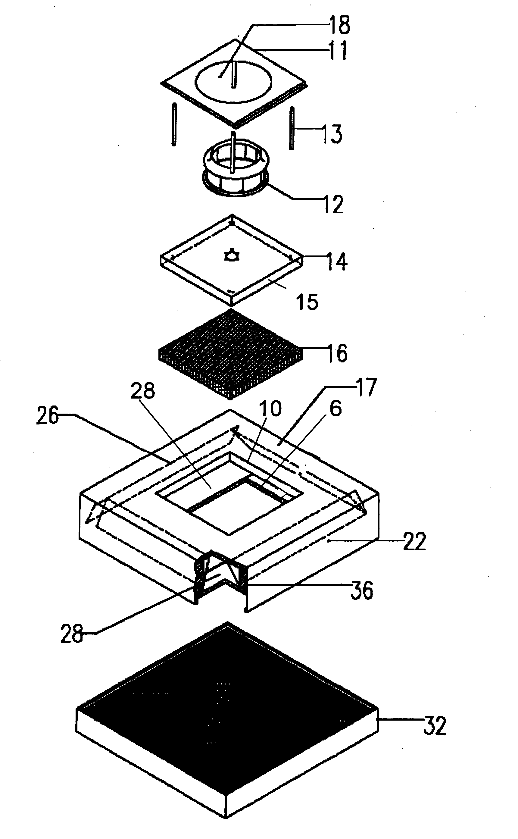
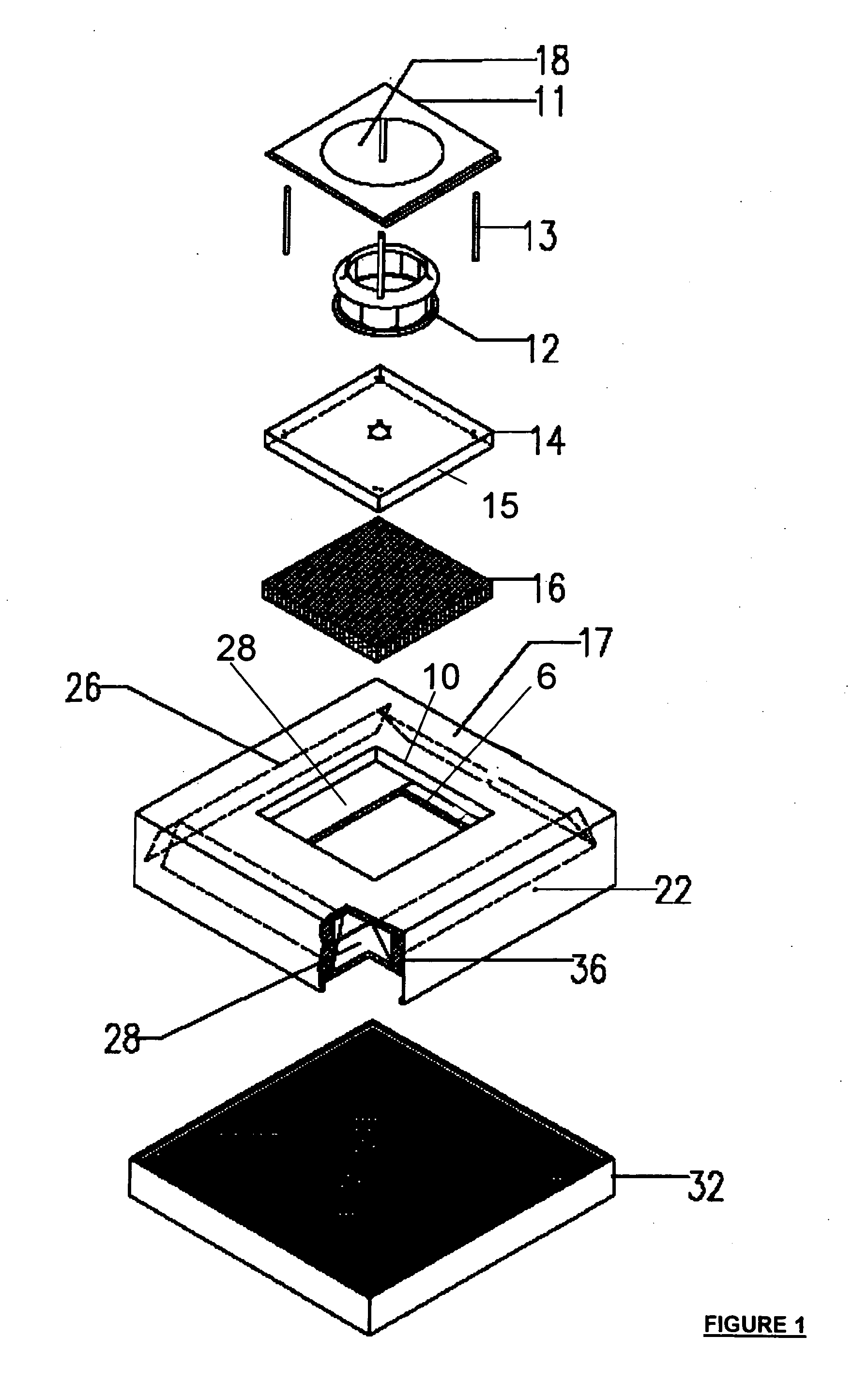
[0029]FIG. 1 is an exploded, front, perspective view of a preferred embodiment the present invention integrated as part of a fan unit. The fan unit comprises four mutually perpendicular side walls 22, and an annular top 17 having a central opening 10. Although the fan unit is shown as being square in shape, it may be of any suitable shape such as, for example, cylindrical, triangular, rectangular, pentagonal, octagonal, and so forth.

[0030] The central opening 10 is shown as being square. It also may be of any suitable shape such as, for example, round, triangular, rectangular, pentagonal, octagonal, and s...


PUM


Abstract

A fan unit comprises a top having an inlet opening, at least one side for enclosing the fan unit, and an outlet opening. A fan blower is disposed on a blower mounting, the fan blower being for drawing air through the inlet opening and for discharging air through the outlet opening. At least one pair of guide baffles extends inwardly from a lower end of the at least one side towards the outlet opening, the pair of guide baffles and the blower mounting forms an air flow channel therebetween. The air flow channel creates a constriction on air flow to raise air pressure within the air flow channel. This creates substantially mono-directional air flow in the air flow channel and through the outlet opening. The air flow therefore has reduced turbulence such that noise from said fan unit is minimised.

Description

FIELD OF THE INVENTION [0001] The present invention relates to a fan unit air flow control and refers particularly, though not exclusively, to a fan unit air flow control for reducing noise from a fan unit in a clean room facility. BACKGROUND OF THE INVENTION [0002] It is common for modern production and testing facilities to control the quantity of particles in the air that circulates within clean room facility in order to ensure the quality of the output of the clean room facility. Whether be it wafer dies, compact discs or memory disk drives, effective fan units are needed to not only keep the particle content within the clean room at acceptable levels, but also to circulate the air which workers breathe. As such, the fan units tend to be relatively powerful. [0003] However, such powerful fan units create excessive noise. Insulation material has been used to line the internal sides of the casing of the fan units to reduce the noise generated by the fan blowers. However, such an e...

Claims


Application Information

Patent Timeline
Patent Type & Authority Applications(United States)
IPC IPC(8): F04D17/16F04D29/42F04D29/66G05D7/00G05D7/06
CPCF04D17/165F04D29/664F04D29/4253
Inventor LEE, ZONG TANG
Owner KYODO ALLIED IND LTD
Why Eureka
Try Eureka