Especially, when an operation is performed in a narrow place, the hook portion hinders an operator from performing an operation.
Thus, the conventional power tool has a problem in that the workability is lowered.
Further, because the hook portion is an obstacle to an operation, a certain conventional power tool is adapted so that the hook portion is detached therefrom as needs arise.
However, such a conventional power tool has encountered a problem in that the hook portion is missing.
On the other hand, a tip end of the tip tool, such as the bit, is liable to damage in a screwing operation.
However, it is trouble some that a bit attached to the power tool used during high-place work performed on a stepladder and a
scaffold is replaced with another bit put on the ground.
Further, in the case that a replacement bit is put into a pocket, there is high possibility that the replacement bit is dropped and lost when, for instance, screws are taken out of the pocket.
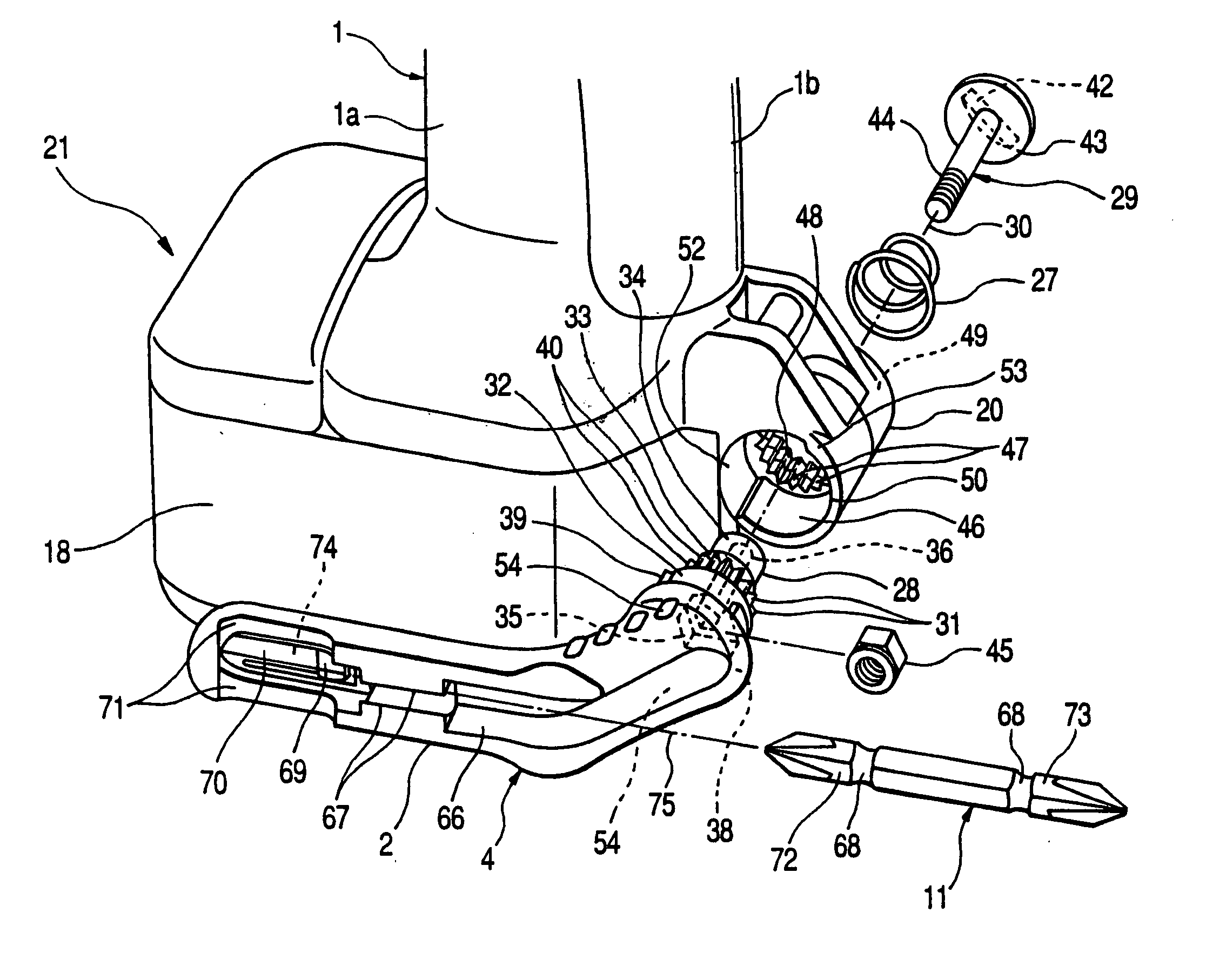
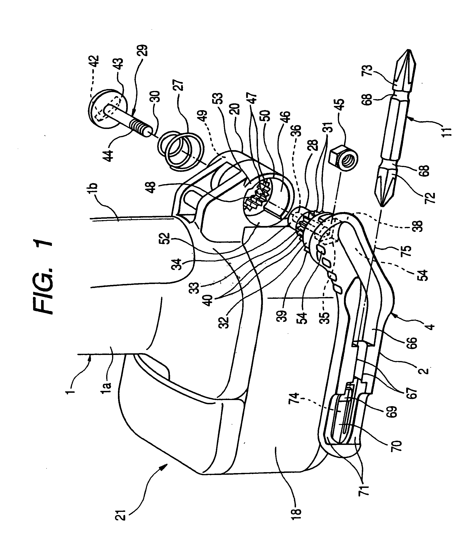
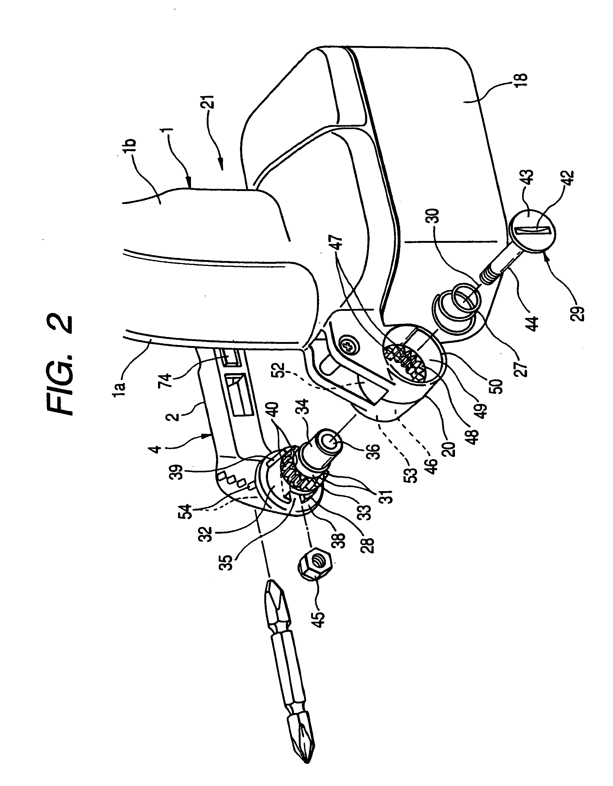
The hook portion shown in FIG. 17 has encountered a problem that each time when the catching piece is turned for
accommodation, pullout, and adjustment thereof, it is necessary and troublesome to perform an operation of rotating a holding nut by using a tool, such as a spanner.
Thus, this conventional hook portion has encountered a problem that the size of the power tool increases.
Thus, this conventional hook portion has encountered a problem that when a force is applied in the turning direction of the hook, the hook is easily rotated and unstable.
Furthermore, this conventional hook portion has encountered another problem that when the hook is locked by a manually-operated lock knob, an operator needs to turn the hook by using one hand during the lock state is canceled by using the other hand, and that thus the
operability thereof is poor.
Thus, this conventional hook portion has encountered a problem that when a force is applied to the hook in the turning direction, the hook is easily turned and thus has poor stability.
In this case, this hook portion has encountered another problem in that the holding portion provided at the side, at which no hook is attached, hinders the operation.
The motor housing has no space, in which the bit is embedded, and is slid into a narrow space, in which a screwing operation is performed, so that the motor housing is unsuitable for being provided in such a way as to project from the tool body.
When provided in the
handle, the bit accommodating portion becomes hard to grasp.
However, this conventional power tool has encountered a problem that when the hook shown in, for example, FIG. 17 is provided in such a power tool, a pull-out piece (see FIG. 17) of the hook hits and is in the way of accessing the bit accommodating portion.
Moreover, this conventional power tool has encountered another problem that even when the pull-out piece (see FIG. 17) is provided at the side of the bit accommodating portion, a portable tool is not compact and thus, the efficiency in space utilization is poor.
Furthermore, when the
metal latch fitting disclosed in JP-A-9-216171 is used, the cost and time needed for assembling the fitting to the tool are high.
However, this conventional power tool has encountered a problem that when the
metal latch fitting is simply replaced with a resin-molded latch fitting, the strength of the resin is lower than that of the iron and that it is thus necessary to increase the thickness of a resin layer to the extent that the fitting can hold the bit.
Thus, this conventional power tool has encountered another problem that such contradictory necessities for setting the thickness of the resin fitting arise.
However, when the bit accommodating portion disclosed in, for instance, JP-A-9-216171 is provided in the catching piece, this conventional power tool has encountered another problem that the bit is covered with the soft material and thus disabled to be detached therefrom, and that even when a part of the soft material is
cut out, a the bit accommodating portion is cracked from the place at which the soft material is
cut by performing an assembling operation or by wear.


