Roof rack for a sport utility vehicle

a technology for sport utility vehicles and roof racks, which is applied to vehicle components, vehicle components, supplementary fittings, etc., can solve the problems of inability time-consuming and often difficult procedures, and the tops cannot be operated to move past the cross members of the rack between their open and closed positions, etc., to achieve convenient and quick pivoted, easy loading and unloading of gear, and simple and convenient arrangement

Inactive Publication Date: 2005-05-05
BESTOP
View PDF15 Cites 67 Cited by
  • Summary
  • Abstract
  • Description
  • Claims
  • Application Information

AI Technical Summary

Benefits of technology

[0007] This invention involves a roof rack for a sport utility vehicle. The rack includes a main frame attached to the vehicle and a plurality of elongated rack portions or cross pieces pivotally mounted to the main frame. In operation, the rack portions can be positioned to extend horizontally across the vehicle above the roof line of the vehicle top to support or carry gear and other items. When desired, the rack portions can be easily and quickly pivoted to a substantially vertical position outboard of the vehicle and out of the path of movement of the vehicle top. The top (or any portion of it such as a sunroof) can then be moved as intended between its open and closed positions and the rack portions pivoted back in place to extend horizontally across the vehicle. This can all be done without having to unload any gear or other items being carried by the rack portions.
[0008] Each rack portion preferably has two, concentrically mounted members that can be slid axially relative to each other. In moving each rack portion from its horizontal position extending over the vehicle to its vertical position outboard of the vehicle, the outer of the two, concentric members can first be slid horizontally relative to the inner member toward the side of the vehicle. As the outer member approaches or reaches an outboard location, the weight of the rack portion and any load on it is then redistributed from being over the vehicle to being partially outboard of the vehicle. The rack portion in this regard is pivotally mounted to the main frame adjacent the side of the vehicle. The weight is therefore shifted from being over the vehicle and only on one side of the pivot to being partially outboard of the vehicle and more balanced on each side of the pivot. Consequently and with the weight of the rack portion and any load on it so redistributed, the operator can then easily move the pivotally mounted rack portion to its vertical position.
[0009] The roof rack of the present invention also has a simple and convenient arrangement to maintain each rack portion in its horizontal position over the vehicle and a locking mechanism to further aid in holding it in place. In an additional embodiment of the invention, a retractable member is provided to selectively engage the vehicle to hold the rack portions and attached trays in an inclined position for easier loading and unloading of the gear and other items.

Problems solved by technology

The main frame and cross members typically cannot then be removed from their position on the vehicle without tools and without undergoing a rather time consuming and often difficult procedure.
Consequently, with the main frame and cross members permanently mounted in place and with vehicle tops (particularly soft tops) that are designed to pivot upwardly as they are opened or closed, the tops cannot be operated to move past the cross members of the rack between their open and closed positions.
Main frames in this regard are often of substantial weight by themselves and unless the gear is unloaded, the user may simply be physically unable to pivot the main frame, attached cross members, and carried items.
Having to unload and re-load the items or trays every time the vehicle top is opened or closed is obviously a drawback to such pivoting systems.
Additionally, the main frames are usually of considerable size and bulk and pivoting them to an out of the way position and back usually requires two or more people.

Method used


Image

  • Roof rack for a sport utility vehicle
  • Roof rack for a sport utility vehicle
  • Roof rack for a sport utility vehicle

Examples


Embodiment Construction

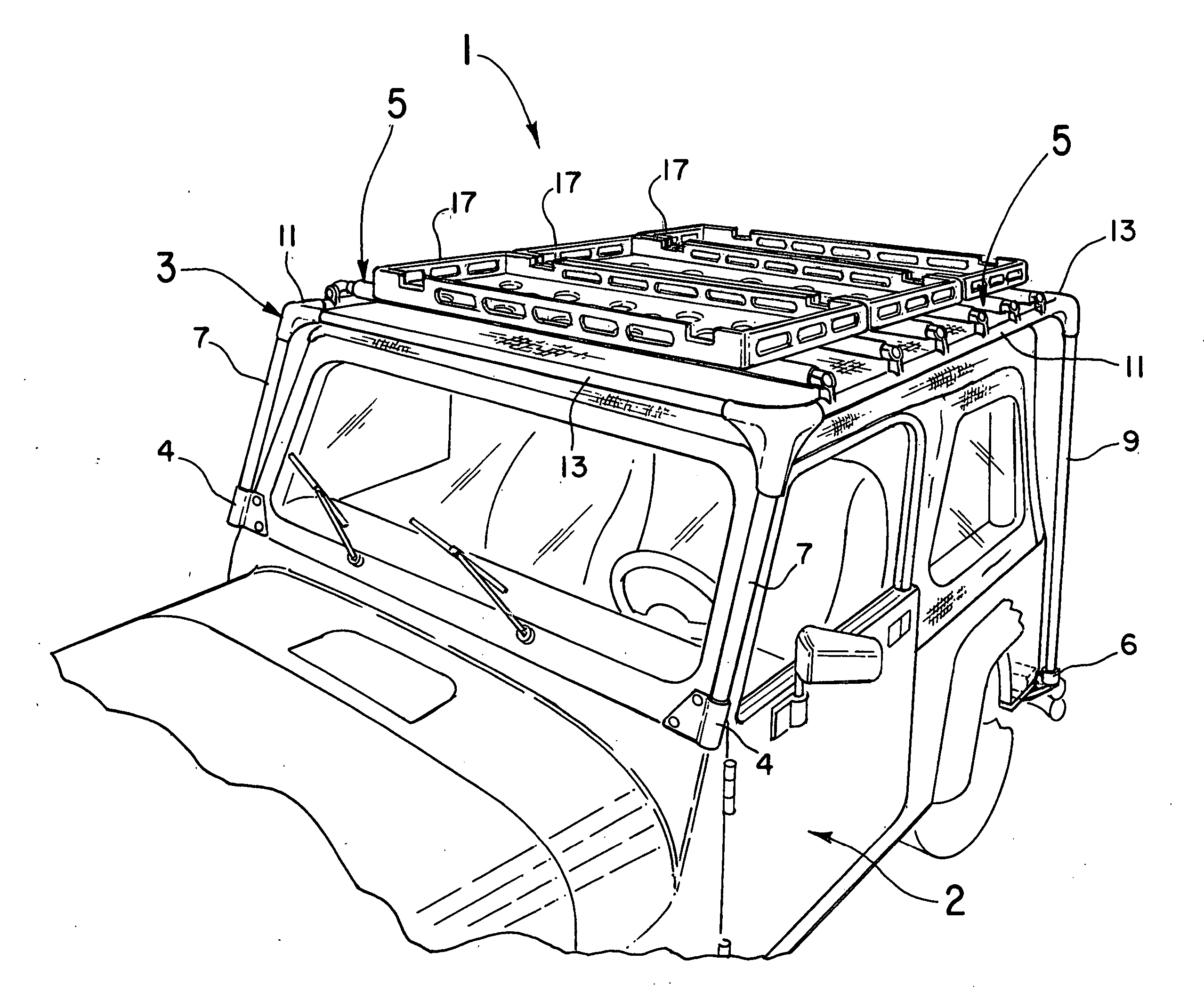
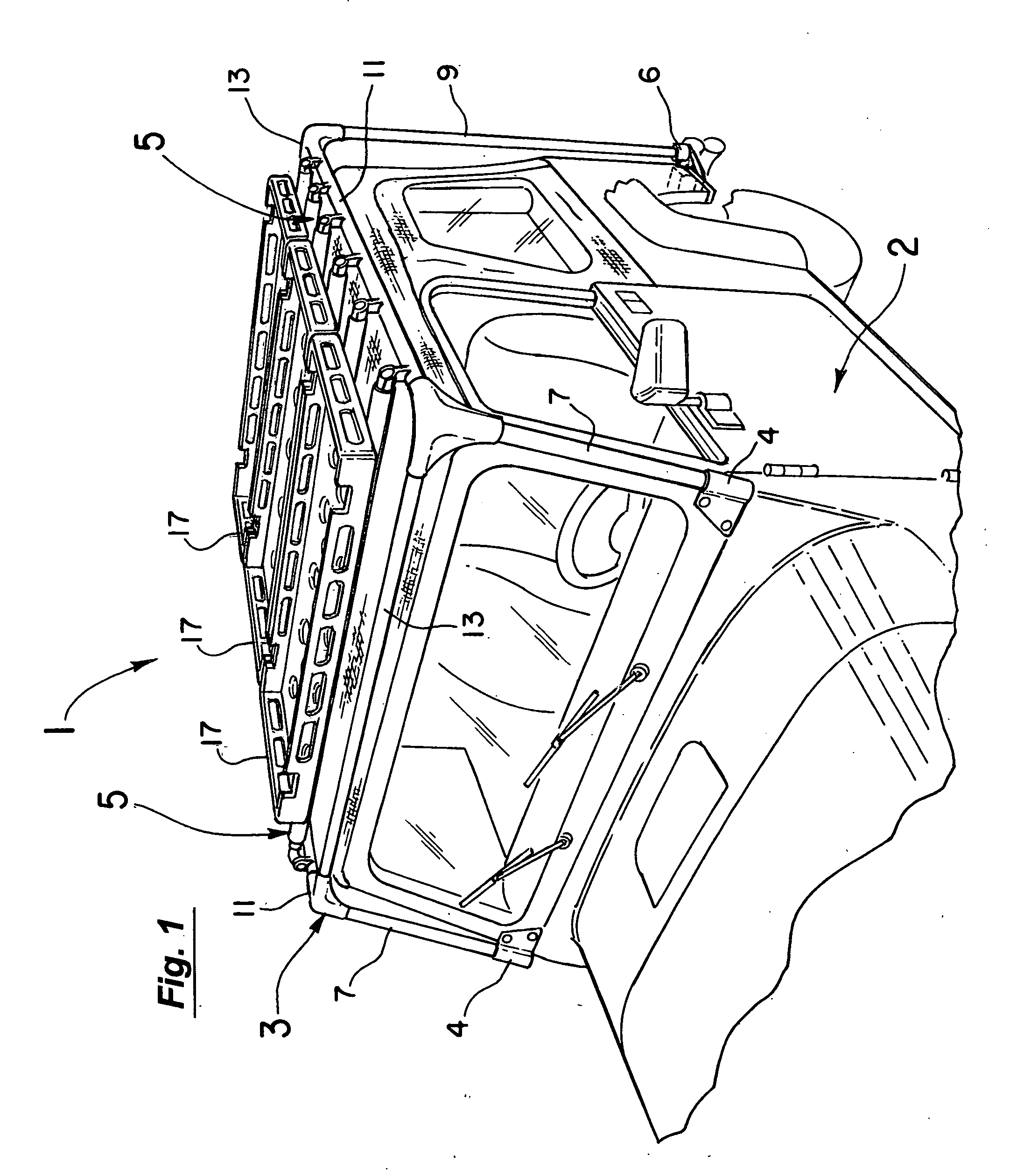
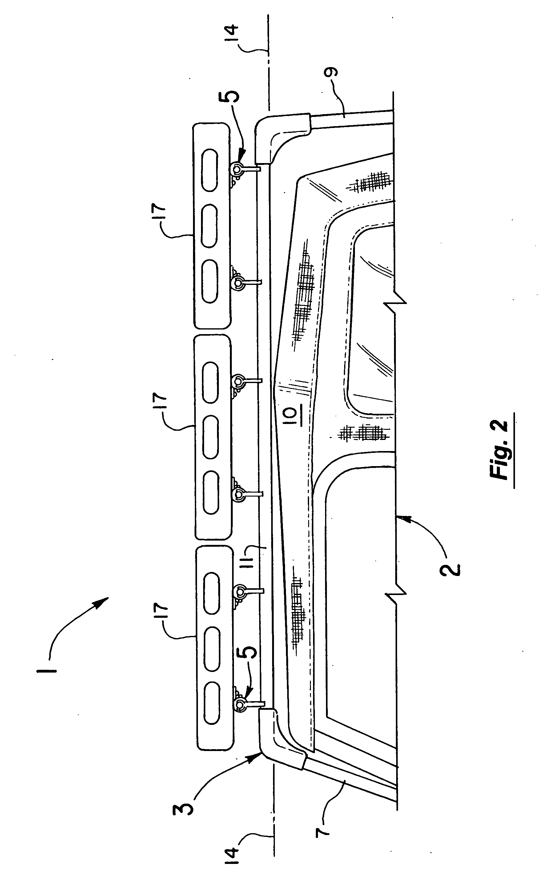
[0027] As shown in FIGS. 1 and 2, the present invention includes a roof rack 1 for a vehicle 2. The roof rack 1 preferably has a main frame 3 mounted to the vehicle 2 and a plurality of elongated rack portions 5 extending across the top of the vehicle 2. The main frame 3 can be secured to the vehicle 2 in any number of ways. However, in the illustrated manner of FIGS. 1 and 2, the main frame 3 has a pair of vertically extending front and rear members 7 and 9 (see FIG. 1). The front members 7 in this regard can be fixedly attached to the vehicle 2 adjacent the base of the windshield by brackets 4. Similarly, the rear members 9 can be fixedly attached adjacent the rear 6 of the body of the vehicle 2. Substantially horizontal side members 11 and cross members 13 then extend between the vertical members 7 and 9 as shown creating the overall shape of the main frame 3. The rack portions 5 are movable as explained below but in the position of FIGS. 1 and 2, each elongated rack portion 5 ex...


PUM


Abstract

A roof rack for a sport utility vehicle. The rack includes a main frame attached to the vehicle and a plurality of rack portions or cross pieces pivotally mounted to the main frame. In use, the rack portions with the gear or carrying trays supported on them can be pivoted to one side of the vehicle and out of the path of the normal movement of the vehicle top including any sunroof. The top or sun roof can then be easily and quickly moved as intended between its open and closed positions without having to unload and reload the stored gear or other items.

Description

BACKGROUND OF THE INVENTION [0001] 1. Field of the Invention [0002] This invention relates to the field of roof racks for sport utility and similar vehicles and more particularly to the field of such racks that are mounted for movement relative to the vehicle. [0003] 2. Discussion of the Background. In most sport utility vehicles, carrying or storage space for gear and other items for camping, hunting, and the like is at a premium. Presently, it is common to store as much gear as possible in the rear of the vehicle and / or provide exterior racks such as roof racks to carry the gear. Current roof racks for the most part involve a main frame attached to the body of the vehicle and rack members extending across the main frame above the vehicle top. The gear or other items are then carried directly on the cross members of the rack or in trays supported on them. [0004] In some designs, arrangements are provided so that the trays or carried items are mounted on additional members of the ra...

Claims


Application Information

Patent Timeline
Patent Type & Authority Applications(United States)
IPC IPC(8): B60R9/00
CPCB60R9/00
Inventor ESSIG, RICHARD C.
Owner BESTOP
Why Eureka
Try Eureka