
Imaging apparatus and method capable of reading out a plurality of regions

Inactive Publication Date: 2005-05-05
TOSHIBA TELI CORP
View PDF11 Cites 3 Cited by
  • Summary
  • Abstract
  • Description
  • Claims
  • Application Information

AI Technical Summary

Benefits of technology

[0009] It is hence an aspect of the invention to provide an imaging apparatus and method capable of limiting imaging signals obtained from an imaging unit to signals from arbitrary plural regions in an imaging plane, checking local images easily, and processing signals at high speed.

Problems solved by technology

Accordingly, in the monitoring system, since the entire screen is always displayed, local checking of the image is difficult, and also in the parts inspection system, since the imaging signal of the entire screen is processed, it is hard to inspect at high speed.

Method used


Image

  • Imaging apparatus and method capable of reading out a plurality of regions
  • Imaging apparatus and method capable of reading out a plurality of regions
  • Imaging apparatus and method capable of reading out a plurality of regions

Examples


Embodiment Construction

[0022] Referring now to the drawings, an embodiment of the present invention will be described detail below.

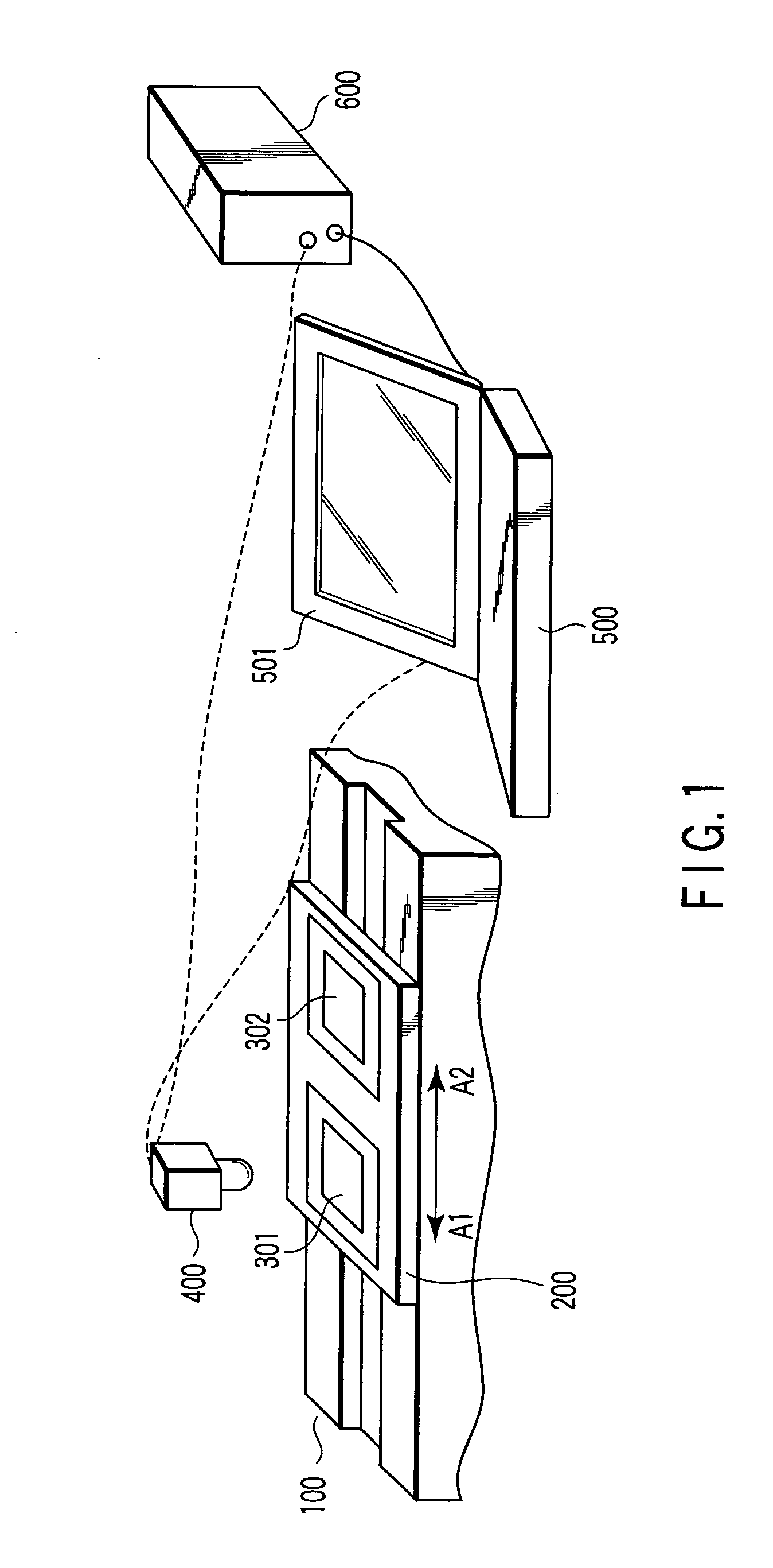
[0023]FIG. 1 shows a simplified configuration of a parts inspection apparatus to which the invention is applied. Reference numeral 100 is an inspection table, and a carrier board 200 is placed on the top of the inspection table 100, and this carrier board 200 is free to move in the direction of arrow A1-A2 in the diagram, and is automatically controlled by a control unit (not shown).

[0024] Test pieces 301, 302 can be put on the top of the carrier board 200. A camera 400 is located at a predetermined position above the inspection table 100. The carrier board 200 can transfer the test pieces 301 and 302 selectively to the lower part of the camera 400 and stop. The camera 400 takes the top of the test piece 301 or 302, and outputs an image signal. The image signal is input into, for example, a personal computer 500, and is shown as an image on a display 501.

[0025] Reference nu...


PUM


Abstract

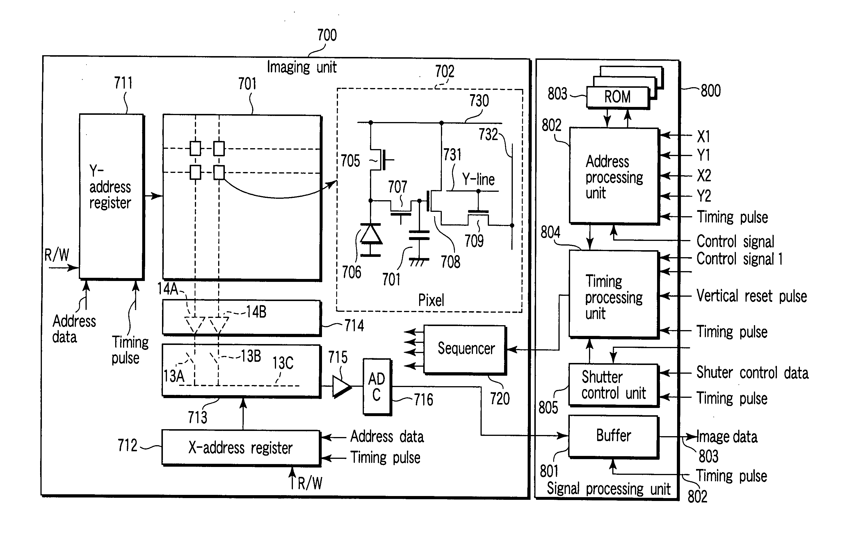
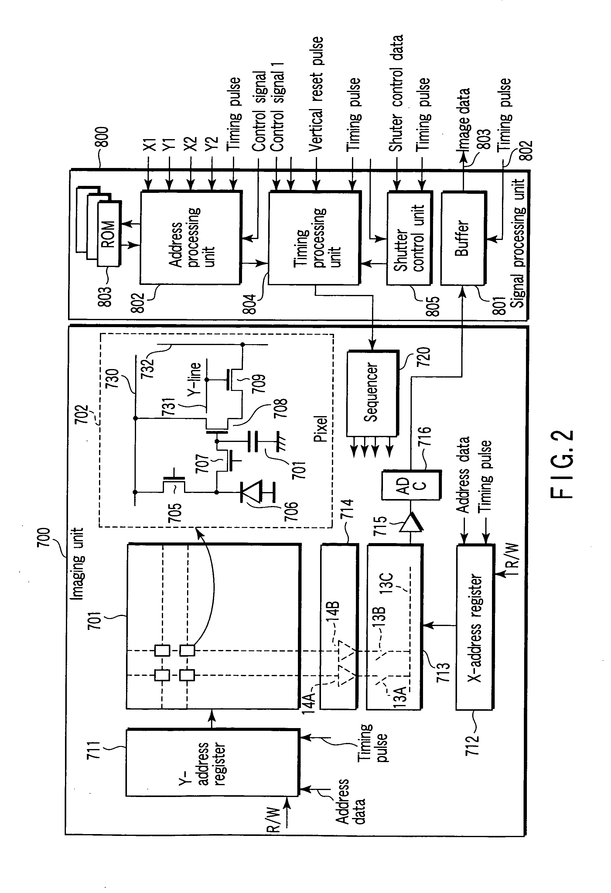
An imaging unit has a plurality of pixels arrayed two-dimensionally therein, and each pixel has an independent address, and is formed such that each pixel may be assigned with a reading address. A signal processing unit can generate an address for specifying arbitrary plural regions in the imaging region when an imaging signal is read out from the imaging unit.

Description

CROSS REFERENCE TO RELATED APPLICATIONS [0001] This is a Continuation Application of PCT Application No. PCT / JP03 / 03732, filed Mar. 26, 2003, which was published under PCT Article 21(2) in Japanese. [0002] This application is based upon and claims the benefit of priority from prior Japanese Patent Application No. 2002-172794, filed Jun. 13, 2002, the entire contents of which are incorporated herein by reference. BACKGROUND OF THE INVENTION [0003] 1. Field of the Invention [0004] The present invention relates to an imaging apparatus and an imaging method, especially using, for example, a CMOS sensor in an imaging unit. More particularly, the invention is applicable as a monitoring apparatus. It can be also used as a parts inspection machine for electronic devices such as a liquid crystal device and a semiconductor device. [0005] 2. Description of the Related Art [0006] As an imaging apparatus using photoelectric conversion elements, a CCD type imaging apparatus and a CMOS type imagin...

Claims


Application Information

Patent Timeline
IPC IPC(8): H04N5/225H04N5/335H04N5/345H04N5/374H04N5/376
CPCH04N3/1562H04N25/44H04N25/745
Inventor ABE, KOUKIKUMAZAWA, TAKASHIMAKINO, SEIKISHI, JUNJI
Owner TOSHIBA TELI CORP
Learn More