Electromechanical micromirror devices and methods of manufacturing the same

a micromirror and electromechanical technology, applied in the field of electromechanical micromirror devices, can solve the problems of difficult control of the gap between the mirror and the mirror addressing electrode, unstable memory cells of the cmos in a high-intensity light environment, etc., to improve the optical isolation of the control circuit area, improve the manufacturing yield, and improve the effect of dielectric isolation

Inactive Publication Date: 2005-05-05
ISHII FUSAO
View PDF18 Cites 20 Cited by
  • Summary
  • Abstract
  • Description
  • Claims
  • Application Information

AI Technical Summary

Benefits of technology

[0017] A 1st advantage of the present invention is that it provides improved dielectric isolation between the control circuit and the micromirror. A 2nd advantage of the present invention is that provides improved optical isolation of the control circuit area. This is particularly advantageous when the micromirror array is used as a spatial light modulator (SLM) and the 1st surface (the micromirror side) is exposed to high intensity radiation. A 3rd advantage of the present invention is that it provides improved manufacturing yields because the control circuit manufacturing processes and micromirror manufacturing processes can be substantially isolated from each other. In other words, manufacturing artifacts arising from the control circuit process will not damage the micro

Problems solved by technology

There may be manufacturing problems associated with the fabrication of micromirrors on top of CMOS circuits.
The placement of CMOS circuits directly under the micromirrors is also responsible for problems of photosensitivity.
As discussed in U.S. Pat. No. 6,344,67

Method used


Image

  • Electromechanical micromirror devices and methods of manufacturing the same
  • Electromechanical micromirror devices and methods of manufacturing the same
  • Electromechanical micromirror devices and methods of manufacturing the same

Examples


Embodiment Construction

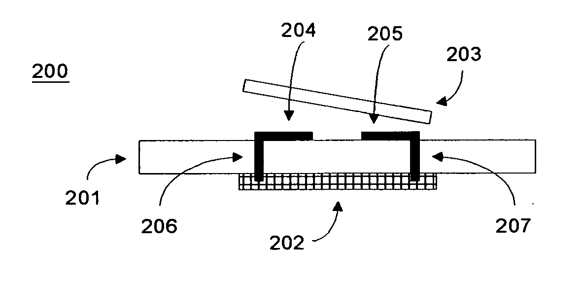
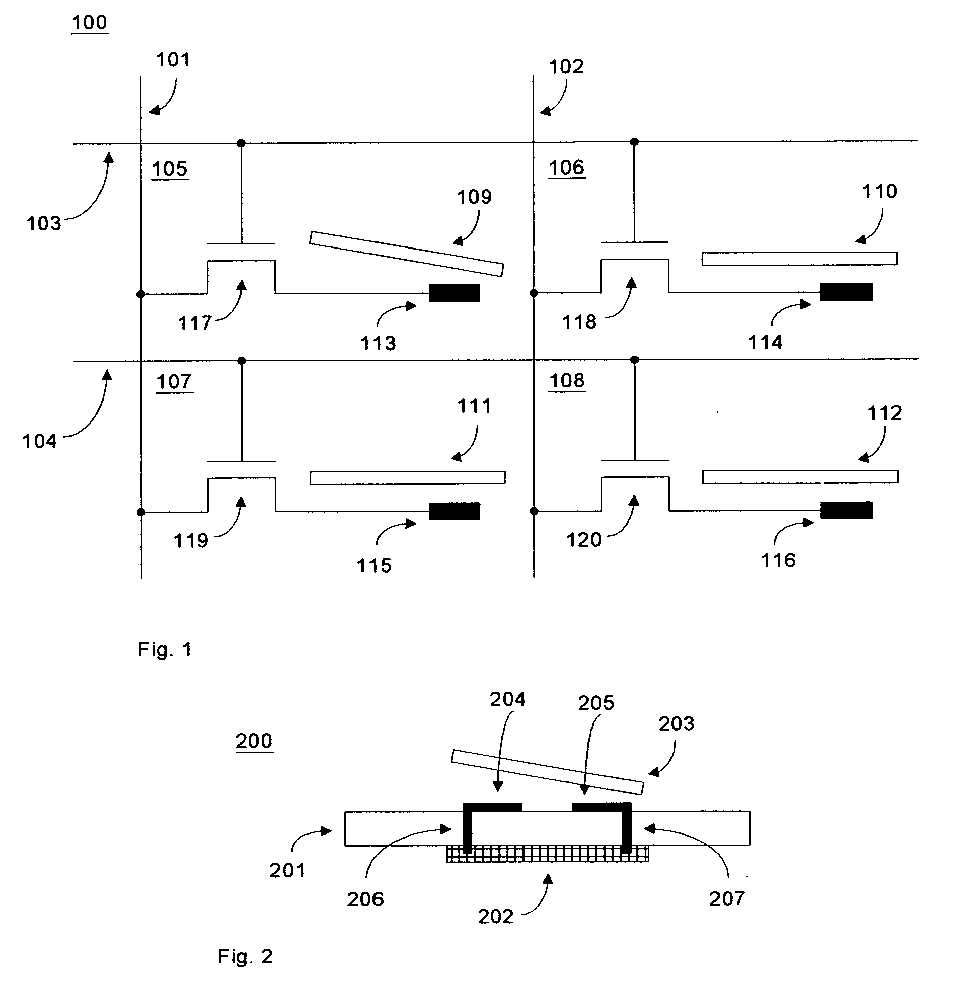
[0034] The present invention relates to electromechanical micromirror devices and arrays of such devices. Shown schematically in FIG. 1 is an array 100 comprising vertical data lines (101 and 102) and horizontal addressing lines (103 and 104), with each intersection of these data and addressing lines forming an electromechanical micromirror device (105, 106, 107, and 108). Each micromirror device comprises a micromirror (109, 110, 111, and 112), an addressing electrode (113, 114, 115, and 116), and an NMOS transistor (117, 118, 119, and 120). Micromirror 109 is shown to be in a deflected state while the other micromirrors are in their undeflected states. A possible scheme for addressing the micromirrors is as follows: The micromirrors (109, 110, 111, and 112) are electrically connected to ground. The deflection of a micromirror is determined by the bias voltage between the micromirror and its addressing electrode. The desired bias voltage is set by the voltages on the vertical data ...


PUM


Abstract

An electromechanical micromirror device comprises a device substrate with a 1st surface and a 2nd surface, control circuitry disposed on said 1st surface, and a micromirror disposed on said 2nd surface. Arrays of such micromirror devices are also described and may be used as a spatial light modulators (SLMs). The arrays may be 1 dimensional (linear) or 2 dimensional. Methods of fabricating micromirror devices and arrays of such devices are also disclosed. Such methods generally involve providing a device substrate with a 1st surface and a 2nd surface, fabricating control circuitry on the 1st surface, and fabricating micromirror(s) on the 2nd surface.

Description

TECHNICAL FIELD [0001] This invention relates to electromechanical micromirror devices and methods of manufacturing the same. When fabricated in an array, such devices can be used as a spatial light modulator. BACKGROUND ART [0002] Electromechanical micromirror devices have drawn considerable interest because of their application as spatial light modulators (SLMs). A spatial light modulator requires an array of a relatively large number of such micromirror devices. In general, the number of devices required ranges from 60,000 to several million for each SLM. Despite significant advances that have been made in recent years, there is still a need for improvement in the performance and manufacturing yields of electromechanical micromirror devices. [0003] An example of an early generation prior art device is disclosed in U.S. Pat. No. 4,592,628. U.S. Pat. No. 4,592,628 describes an array of light reflecting devices on a substrate. Each device comprises a hollow post and a deflectable po...

Claims


Application Information

Patent Timeline
IPC IPC(8): G02B26/08
CPCG02B26/0841
Inventor ISHII, FUSAO
Owner ISHII FUSAO
Why Eureka
Try Eureka