Solid immersion lens holder

a technology for solid immersion and lens holder, which is applied in the direction of mountings, microscopes, instruments, etc., can solve the problems of affecting the quality of immersion lens holder, so as to facilitate the exchange of lenses

Inactive Publication Date: 2005-05-05
HAMAMATSU PHOTONICS KK
View PDF19 Cites 24 Cited by
  • Summary
  • Abstract
  • Description
  • Claims
  • Application Information

AI Technical Summary

Benefits of technology

[0020] The arm part may also be detachably connected to the three-dimensional direction moving device. In this case, for lens exchange, exchange of the arm part as a whole is enabled and the lens exchange is facilitated due to not having to handle the minute solid immersion lens.

Problems solved by technology

That is, there are cases where an observed object with which a solid immersion lens is put in close contact becomes cracked or damaged otherwise due to an excessive pressure being applied to the observed object.
Also, since a solid immersion lens is pressed against an observed object, depending on the flatness of the object, observation of high precision is made difficult due to gaps that form between the solid immersion lens and the observed object.
However, if a part at which the gap is large exists in a region in which the bottom surface of the solid immersion lens opposes the rear surface of the semiconductor substrate, the transmitted light intensity drops drastically, only incident light of no more than the critical angle can propagate, and the effective numerical aperture is restricted at this part at which the gap is large.
It thus becomes difficult for the inherent resolution of the solid immersion lens to be exhibited.

Method used


Image

  • Solid immersion lens holder
  • Solid immersion lens holder
  • Solid immersion lens holder

Examples


first embodiment

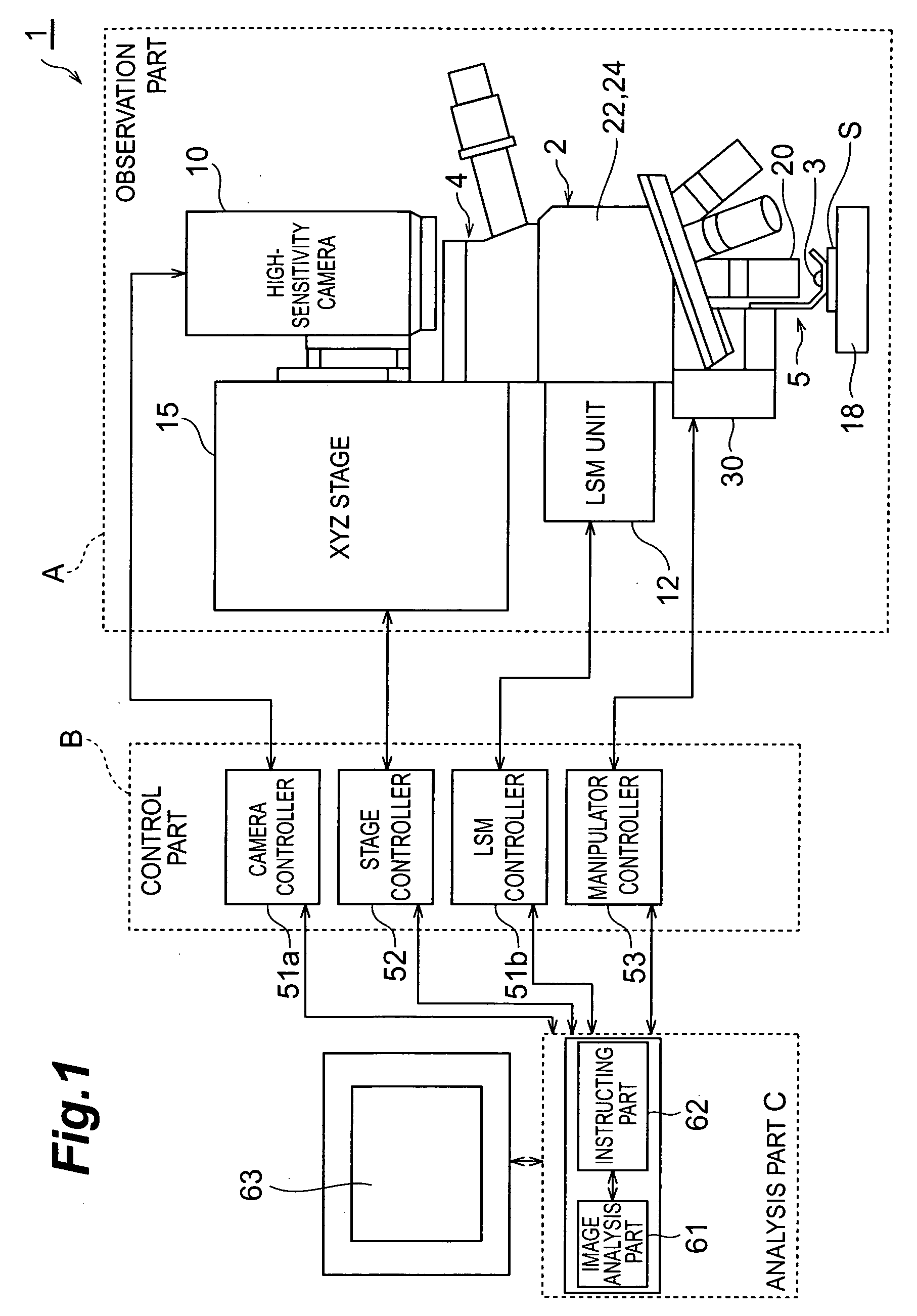
[0046] First, the semiconductor inspection device equipped with the solid immersion lens holder of the first embodiment shall be described. As shown in Fig. 1, semiconductor inspection device 1 is an inspection device, for which the object of observation is a semiconductor device S, wherein a circuit pattern, for example, of a transistor and wiring, etc., is formed, and images of this semiconductor device S are acquired for inspection of the internal information thereof. With this invention, “internal information” shall include circuit patterns of semiconductor devices as well as emission of weak light from semiconductor devices. Such weak light emissions include those caused by an abnormal position due to a defect of a semiconductor device, transient light emission that accompanies the switching operation of a transistor inside a semiconductor device, etc. The generation of heat due to a defect of a semiconductor device is also included.

[0047] This semiconductor inspection device 1...

fourth embodiment

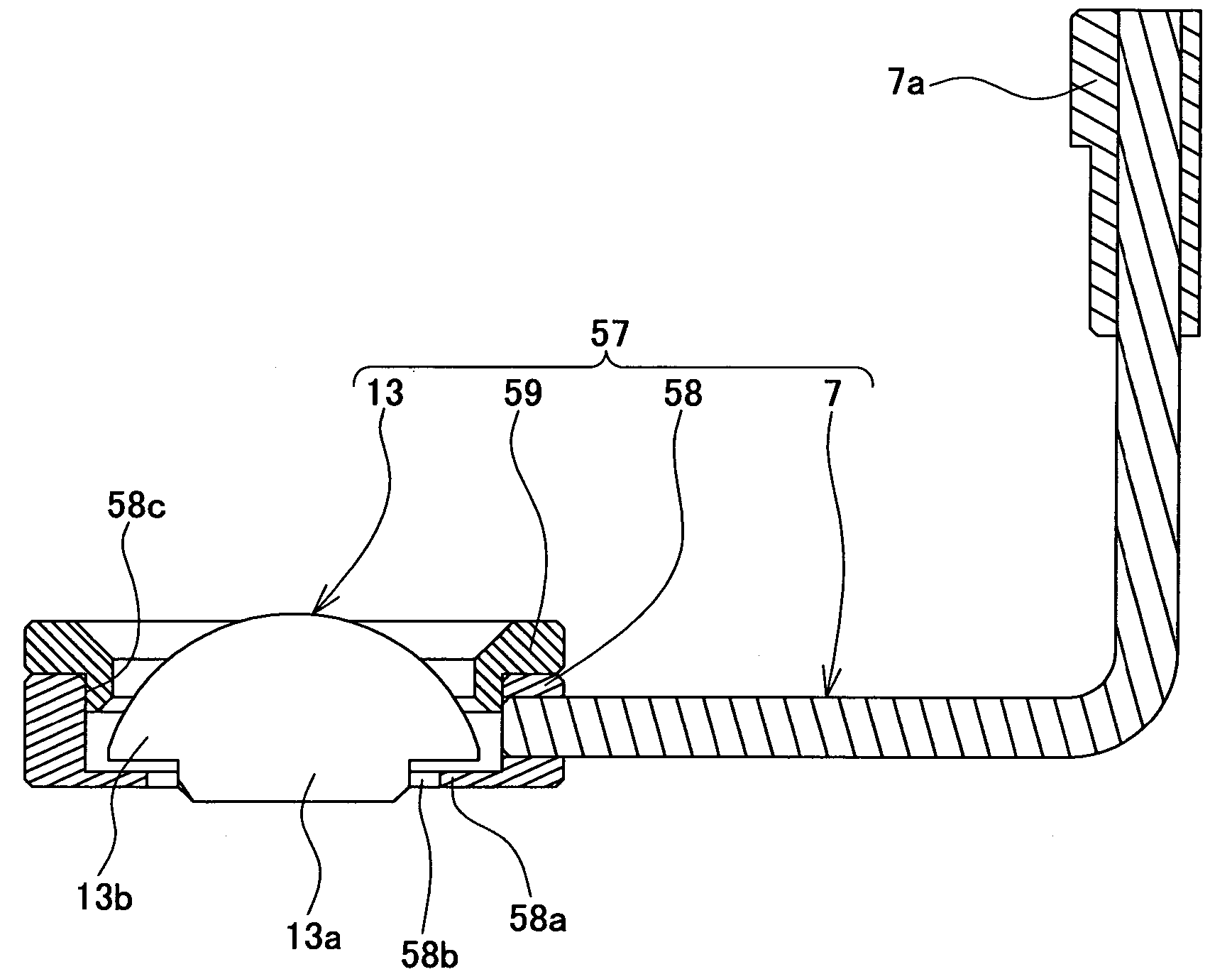
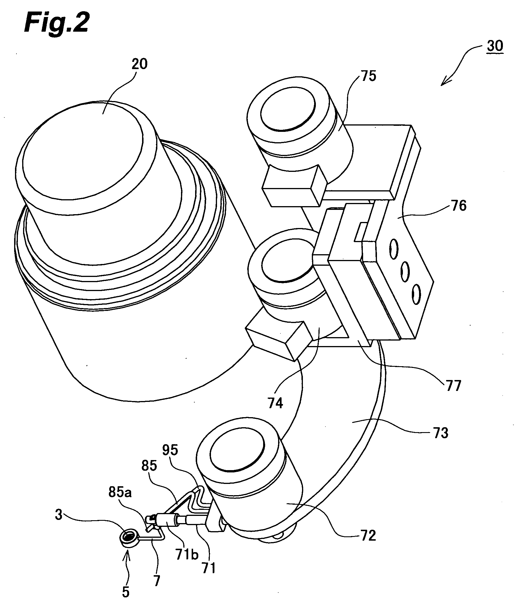
[0112]FIG. 20 is a perspective view showing a solid immersion lens holder of this invention, and FIG. 21 is a vertical section showing the solid immersion lens holder in the state in which a lens is set at a closely contacting position. Also, FIG. 22 is a perspective view showing a part at which the solid immersion lens holder and a solid immersion lens moving device are connected. As shown in FIG. 20 and FIG. 21, solid immersion lens holder 105 is equipped with a holder 106 formed to a substantially cylindrical form, which supports solid immersion lens 103, and an arm part 107, which holds this holder 106.

[0113] As shown in FIG. 21, holder 106 is equipped with a lower holder 108 and an upper holder 109. Of these, upper holder 109 is arranged as an annular part that is formed integral to arm part 107. Lower holder 108, for supporting solid immersion lens 103, is supported by arm part 107 via this upper holder 109. These holders 108 and 109 are formed to substantially cylindrical for...


PUM


Abstract

An arrangement, equipped with a holder 9, which supports a solid immersion lens 3 in the gravity direction with the bottom surface of solid immersion lens 3 being protruded downward through an opening 9b, is provided. With this arrangement, when solid immersion lens 3 is set on an observed object, solid immersion lens 3 is put in a state in which it is raised by the observed object and is made free with respect to holder 9. Also in this state, an excessive pressure will not be applied to the observed object and yet solid immersion lens 3 is put in close contact in conformance with the observed object and temperature drifts at the holder 9 side or the observed object side are cut off from the counterpart side and thus the influences of such temperature drifts are eliminated. A solid immersion lens holder, with which the damaging of the observed object can be eliminated and which enables high-precision observation, is thus provided.

Description

BACKGROUND OF THE INVENTION [0001] 1. Field of the Invention [0002] This invention concerns a holder for a solid immersion lens. [0003] 2. Related Background of the Invention [0004] A solid immersion lens (SIL) is known as a lens for magnifying an image of an observed object. This solid immersion lens has a hemispherical shape or a hyperhemispherical shape, called a Weierstrass sphere, and is a microlens with a size of approximately 1 mm to 5 mm. When this solid immersion lens is put in close contact with a surface of an observed object, since both the numerical aperture NA and the magnification are increased, observation at high spatial resolution is enabled. [0005] A device, for which the observed object is a semiconductor wafer and with which a solid immersion lens is put in close contact with a rear surface of the semiconductor wafer to inspect the fine characteristics of the interior of the semiconductor wafer through a microscope, has thus been proposed (see for example, Docum...

Claims


Application Information

Patent Timeline
Patent Type & Authority Applications(United States)
IPC IPC(8): G02B7/14G02B21/33
CPCG02B21/33G02B7/14
Inventor TANABE, HIROSHIARATA, IKUOTERADA, HIROTOSHI
Owner HAMAMATSU PHOTONICS KK
Why Eureka
Try Eureka