Magnetic head

Inactive Publication Date: 2005-05-05
ALPS ALPINE CO LTD
View PDF1 Cites 0 Cited by
  • Summary
  • Abstract
  • Description
  • Claims
  • Application Information

AI Technical Summary

Benefits of technology

[0027] Since the magnetic core has the first and second stepped portions, the narrow core portion offset from the second stepped portions toward the first end of the magnetic core can be worked to be narrow, and the track width of the magnetic gap can be reduced. Moreover, since the terminal end of the magnetic gap is disposed between the second stepped portions between the sliding surface, the depth of the magnetic gap can be reduced, and the strength of a magnetic field

Problems solved by technology

In this structure, however, the depth Gd of the magnetic gap G is too large, the strength of a leakage field applied from the starting end Ga of the magnetic gap G to the recording medium is small, and, for example, overwriting performance is reduced.
Consequently, the recording medium is prone t

Method used


Image

  • Magnetic head
  • Magnetic head
  • Magnetic head

Examples


Example

EXAMPLE

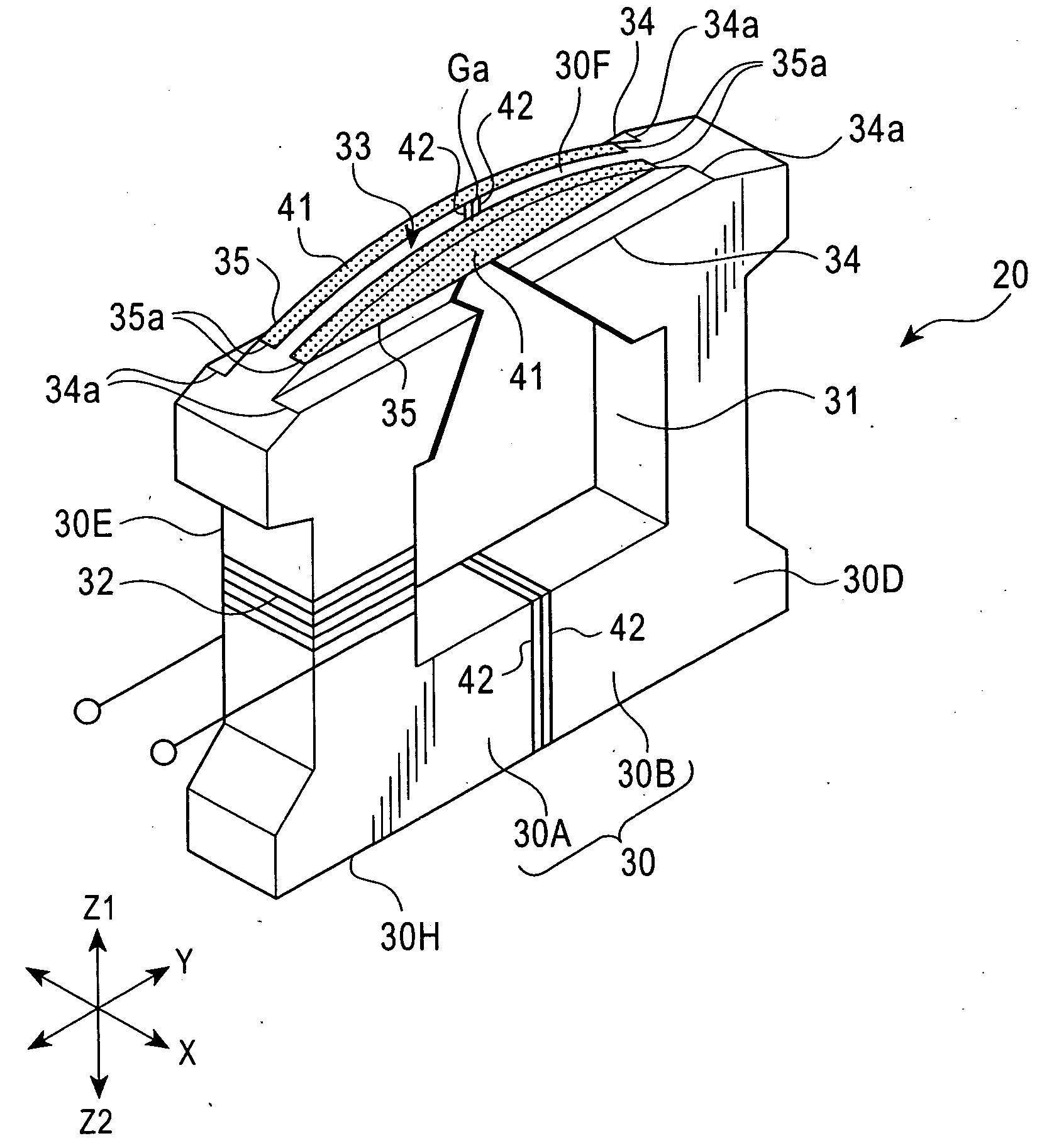
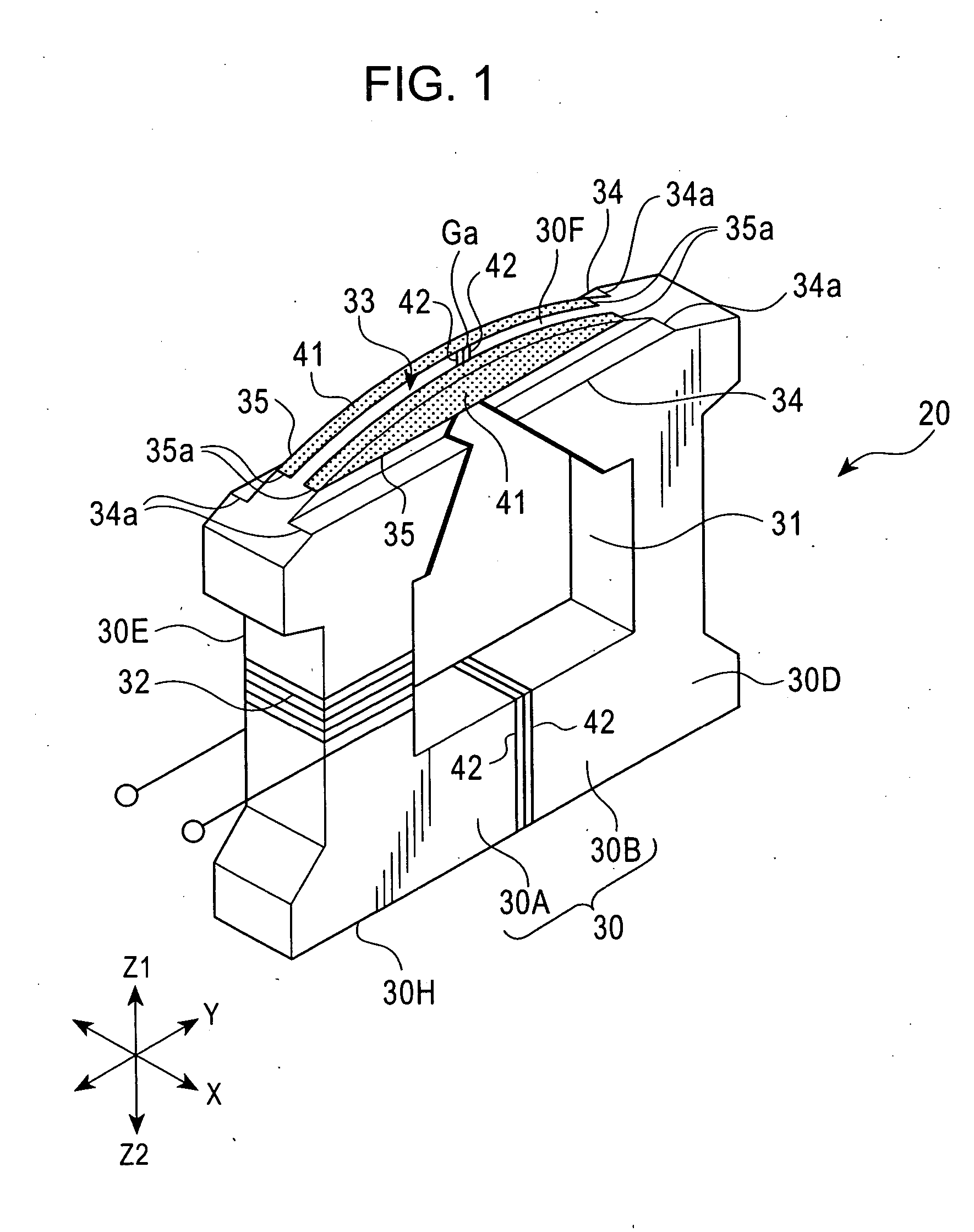
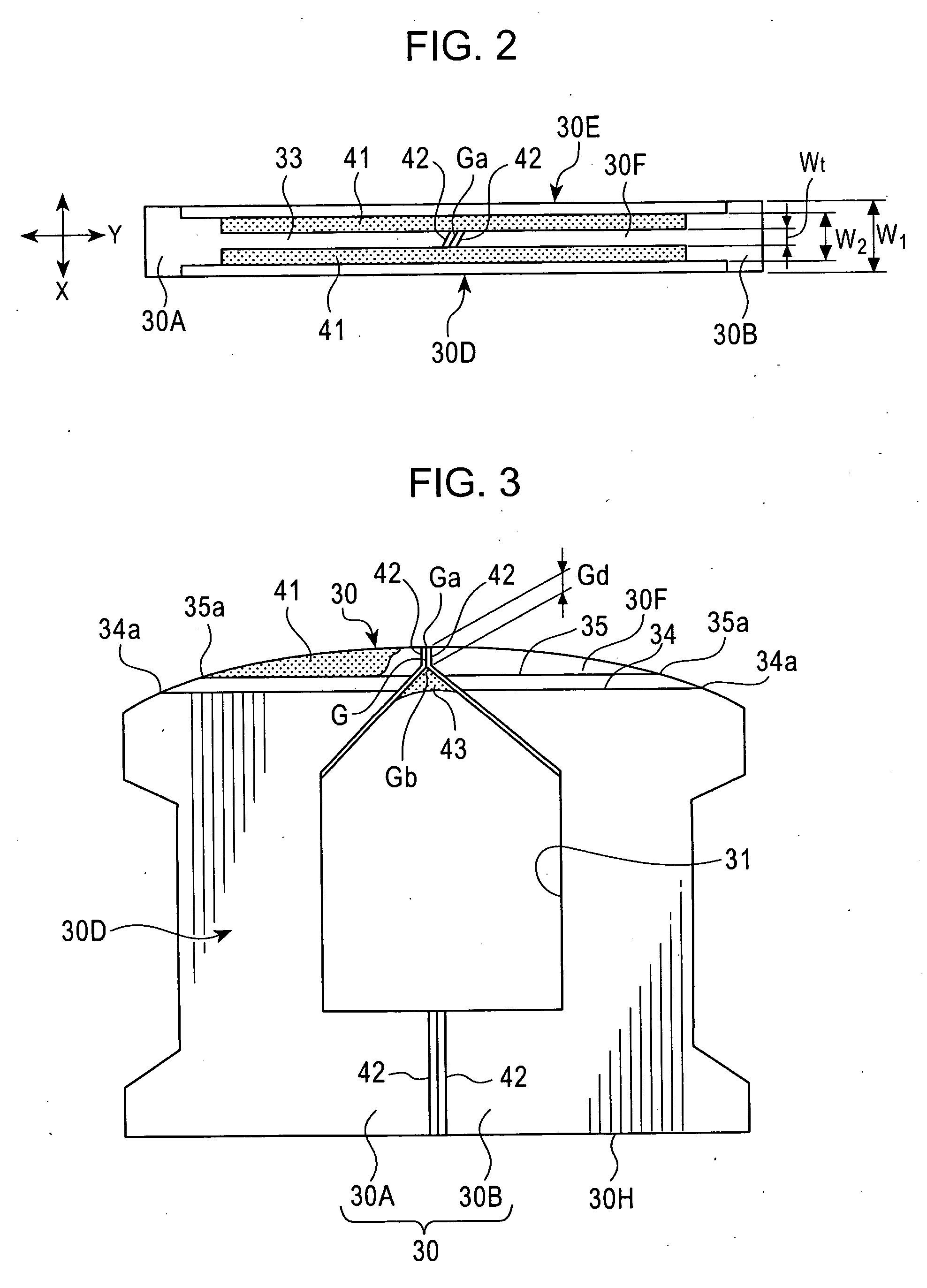
[0065] A plurality of magnetic heads similar to the magnetic head 20 shown in FIGS. 1 to 4. The width Wt of the narrow core portion 30F, that is, the apparent track width was fixed, and the width W2 of the sliding surface 33 was varied among the magnetic heads by changing the width of the nonmagnetic material portions 41. The width W2 of the sliding surface 33 was equal to the sum of the width of the narrow core portion 30F and the widths of the nonmagnetic material portions 41.

Comparative Example

[0066] A magnetic head 60 shown in FIG. 7 was produced. In the magnetic head 60, a sliding surface 61 included a narrow core portion 62 on which a starting end Ga of a magnetic gap G appeared. Nonmagnetic material portions 63 were provided on both sides of the narrow core portion 62, and side core portions 64 were formed of portions of a magnetic core on both sides of the nonmagnetic material portions 63. The curvature of a curve in the X-direction of the sliding surface 61 was se...


PUM


Abstract

In a magnetic head, a magnetic core is formed by joining core halves. The magnetic core includes first stepped portions, second stepped portions, and a narrow core portion. A magnetic gap is provided in the narrow core portion. A terminal end of the magnetic gap is disposed between the second stepped portion and the narrow core portion, and the depth of the magnetic gap is thereby made small. The magnetic gap is reinforced by nonmagnetic material portions on both sides thereof, and a nonmagnetic material.

Description

BACKGROUND OF THE INVENTION [0001] 1. Field of the Invention [0002] The present invention relates to magnetic heads for use in magnetic recording and playback apparatuses such as digital video cameras (DVCs) and tape storages, and more particularly, to a magnetic head having a small track width that is suitable for high-density recording, that constantly touches a tape in a proper manner, and that provides stable playback output performance. [0003] 2. Description of the Related Art The recording density of magnetic recording and playback apparatuses, such as digital video cameras and tape storages, has increased, and correspondingly, the track width of magnetic heads mounted in the magnetic recording and playback apparatuses has decreased. [0004] In a narrow-track magnetic head, the width (thickness) of a portion of a magnetic core that appears on a sliding surface that slides on a recording medium must be decreased in accordance with the track width. [0005] U.S. Pat. No. 5,157,569 ...

Claims


Application Information

Patent Timeline
IPC IPC(8): G11B5/127G11B5/187G11B5/23
CPCG11B5/1871
Inventor SUGIHARA, SHINJI
Owner ALPS ALPINE CO LTD
Why Eureka
Try Eureka