Specially formatted optical disk and method of playback

a special format and optical disk technology, applied in the field of optical disks, can solve the problems of difficult to realize four to eight time speed, difficult for human eyes to recognize images, and inability to realize normal playback speed, etc., and achieve the effect of increasing the special playback speed

Inactive Publication Date: 2005-05-05
INTEL CORP
View PDF12 Cites 11 Cited by
  • Summary
  • Abstract
  • Description
  • Claims
  • Application Information

AI Technical Summary

Benefits of technology

[0028] An object of the invention is to increase the special playback speed.
[0029] Another object of the invention is to reduce rotation waiting time when a track jump is performed.

Problems solved by technology

In the actual image search, if the speed is too high, it is difficult for the human eyes to recognize the image.
Where the compressed data of the MPEG system is used, and if it is attempted to reproduce P-pictures in the encoding structure of FIG. 31 to FIG. 33, the B-pictures positioned before the P-pictures are also read, and it is therefore difficult to realize four to eight time speed.
Furthermore, in the conventional system the amount of data of the I-picture encoded by intra-frame DCT is larger than the amount of data of P- or B-pictures, so that super-fast playback, of several tens times the normal playback speed cannot be realized because the time for inputting data may be insufficient.
Furthermore, as the scene change position in the motion picture image information is not known, a scene-by-scene search for finding a scene cannot be achieved by using the conventional system.
In addition, because only part of the data in each GOP is read in the special playback, image playback may not be accomplished, or playback may be possible only with regard to part of the display screen in the conventional system.

Method used


Image

  • Specially formatted optical disk and method of playback
  • Specially formatted optical disk and method of playback
  • Specially formatted optical disk and method of playback

Examples


embodiment 1

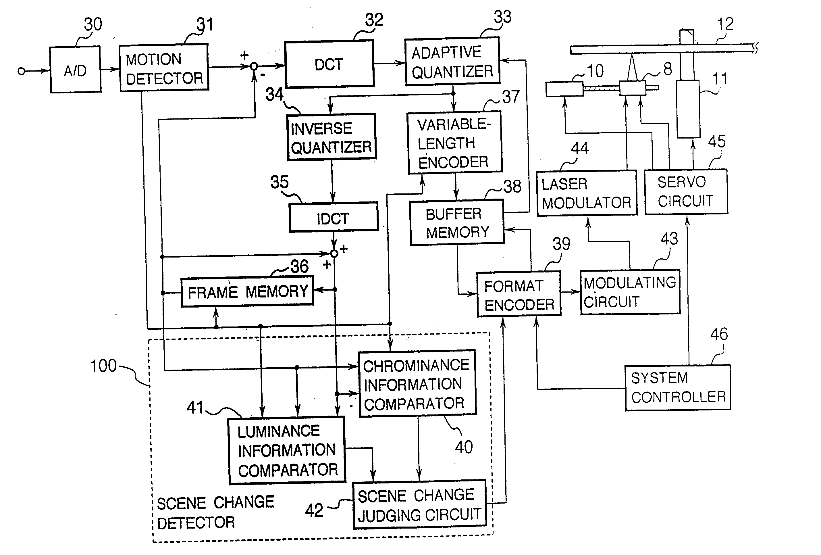
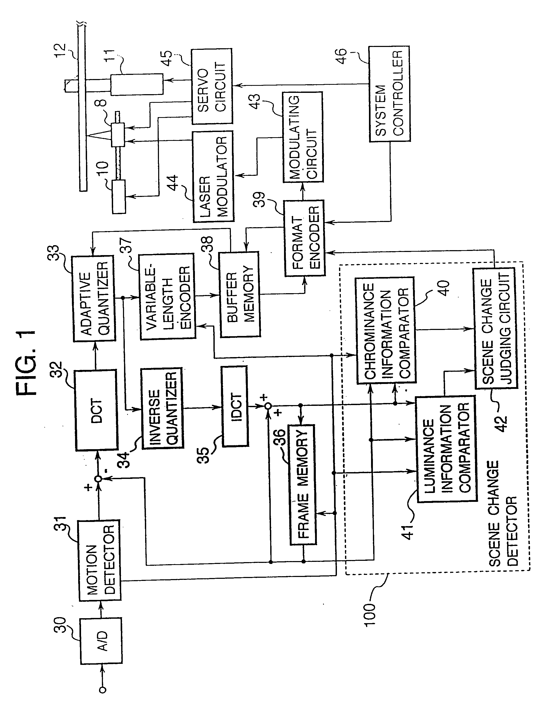
[0145]FIG. 1 is a block diagram showing a recording system of an optical disk device of Embodiment 1 of the present invention. In the drawing, an A / D converter 30 converts an analog video signal into a digital signal. A motion detector 31 detects the motion vector of the digital video signal. A discrete cosine transform circuit 32 divides the image information into horizontal and vertical spatial frequency components. Reference numeral 33 denotes an adaptive quantizer, and 34 denotes an inverse quantizer. An inverse discrete cosine transform circuit 35 restores the image information from the frequency components. A frame memory 36 stores the image information as reference images, on the basis of the motion vector, 37 denotes a variable-length encoder, and 38 denotes a buffer memory. A format encoder 38 appends the address information and attribute data.

[0146] A chrominance information comparator 40 compares the chrominance information of a picture with chrominance information of pr...

embodiment 2

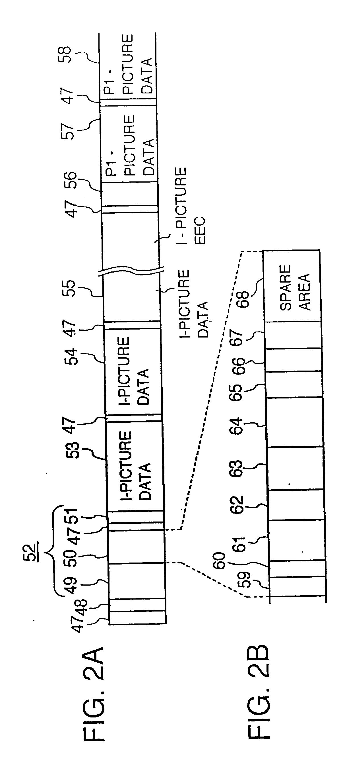
[0164] Embodiment 2 is next described with reference to the drawings. FIG. 7A shows the method of reading data in which the image data recorded in the format of FIG. 2A is fast-played back by track jump, and FIG. 7B shows the disposition of the video headers 52 on the disk, and FIG. 7C shows the track jump at the video header 52.

[0165] In FIG. 8, the order of I- and P-pictures is reversed at every track-adjacent GOP, so that I-picture reproduction at the time of track jump is achieved with a shorter rotation waiting time. A rotation waiting time occurs when, for example, a track jump occurs but the next picture to be reproduced is not located under the optical head 8. Thus, one must wait for the disc 12 to rotate such that the next picture to be reproduced is properly located under the optical head 8. In the drawing, reference numeral 69 denotes an audio header indicating the head of the audio signal, 70 denotes audio data, 71 denotes a video data recognition parity for recognition...

embodiment 3

[0172]FIG. 10 shows a format arrangement on a disk of a continuous groove type in Embodiment 3. FIG. 11 shows a format arrangement on a disk of a sample servo type in Embodiment 3. FIG. 12 is a flowchart showing the operation of reading data in which the disk rotation speed is increased during special playback.

[0173] The operation of Embodiment 3 will next be described. Generally, for the purpose of increasing the recording density of an optical disk, constant linear velocity (CLV) recording is advantageous over constant angular velocity (CAV) recording. However, in CLV recording, the head of image data and the disposition on the I-picture on the disk is not fixed, and because in particular the angular position of the I-pictures is at random, the operation of Embodiment 1 or Embodiment 2 is difficult. The disk is therefore divided into zones, e.g., zones A to F as illustrated in FIG. 10 or FIG. 11, and the head regions of the GOPs within each zone are made to be aligned in the radi...


PUM

PropertyMeasurementUnit
diameteraaaaaaaaaa
timeaaaaaaaaaa
timeaaaaaaaaaa

Abstract

In an optical disk storing digital image information in the form of a succession of blocks, each comprising a plurality of frames comprising I-, P- and B-pictures, wherein an address format is preformatted in front of the block of image information of said plurality of frames, and the data arrangement within each image information blocks is such that I- and P-pictures are collectively disposed. The position of the I-pictures within each block is shifted from one block to another. The I-picture data may be divided into fraction according to the position on the screen, the DCT frequency, or layering, and the fractional I-picture data may be arranged in the image information blocks, and a header or parity signal is recorded in front of each fractional I-picture data. With such a configuration, it is possible to increase the speed of fast playback, and realize smooth playback picture.

Description

BACKGROUND OF THE INVENTION [0001] The present invention relates to an optical disk and a method of playing back from an optical disk. [0002]FIG. 29 is a block diagram showing a conventional optical disk recording / playback device shown in Japanese Patent Kokai Publication 114369 / 1992. An A / D converter 1 converts a video signal, an audio signal or the like into digital information. An information compressing means 2 serves to compress the output of the A / D converter 1. A frame sector converting means 3 converts the compressed information into sector information equal in length to a multiple of the frame period. An encoder 4 encodes the output of the frame sector converting means 3. A modulator 5 modulates the output of the encoder 4 into predefined modulated codes so as to reduce interference between codes on the recording medium. A laser driver 6 is for modulating the laser light in accordance with the modulated codes. A laser output switch 7 is driven by the laser driver 6 to vary ...

Claims


Application Information

Patent Timeline
Patent Type & Authority Applications(United States)
IPC IPC(8): G11B7/0037G11B20/10G11B20/12G11B27/00G11B27/034G11B27/036G11B27/10G11B27/19G11B27/24G11B27/28G11B27/30G11B27/32H04N5/783H04N5/85H04N7/50H04N9/804
CPCG11B7/0037H04N19/61G11B7/08541G11B20/10G11B20/1217G11B20/1251G11B20/1258G11B27/005G11B27/034G11B27/036G11B27/105G11B27/19G11B27/24G11B27/28G11B27/3027G11B27/329G11B2220/20G11B2220/216G11B2220/2525G11B2220/2537H04N5/783H04N5/85H04N9/804H04N9/8042H04N9/8063G11B7/00745
Inventor NAGASAWA, MASATO
Owner INTEL CORP
Why Eureka
Try Eureka