Rotary blood pump

a rotary pump and blood pump technology, applied in the direction of positive displacement liquid engine, piston pump, liquid fuel engine, etc., can solve the problems of blood circulating through the pump with the contact bearing experiencing hemolysis, damage to blood cells, and mechanical contact bearing damage, so as to prolong the life of the pump operation and reduce damage

Active Publication Date: 2005-05-05
TC1 LLC
View PDF45 Cites 57 Cited by
  • Summary
  • Abstract
  • Description
  • Claims
  • Application Information

AI Technical Summary

Benefits of technology

[0008] In view of limitations of known systems and methods, various “contactless” bearing mechanisms are provided for a rotary pump as alternatives to mechanical contact bearings. Various rotor and housing design features are provided to achieve hydrodynamic, hydrostatic, or magnetic bearings. These design features may be combined. The lack of mechanical contact bearings enables longer life pump operation and less damage to working fluids such as blood.

Problems solved by technology

Some working fluids may be damaged by the mechanical contact bearings.
Blood pumped through pumps with contact bearings can experience hemolysis, i.e., damage to blood cells.
Both blood pumps suffer from hydraulic inefficiencies due at least in part to the large, unconventional blade geometry required for disposing the magnets within the impeller blades.
Hydrodynamic bearings can damage blood cells as a result of shear forces related to the load carried by the hydrodynamic bearings despite the lack of contact between the impeller and the pump housing.
Thus exclusive reliance on hydrodynamic bearings may be harmful to the blood.

Method used


Image

  • Rotary blood pump
  • Rotary blood pump
  • Rotary blood pump

Examples


Embodiment Construction

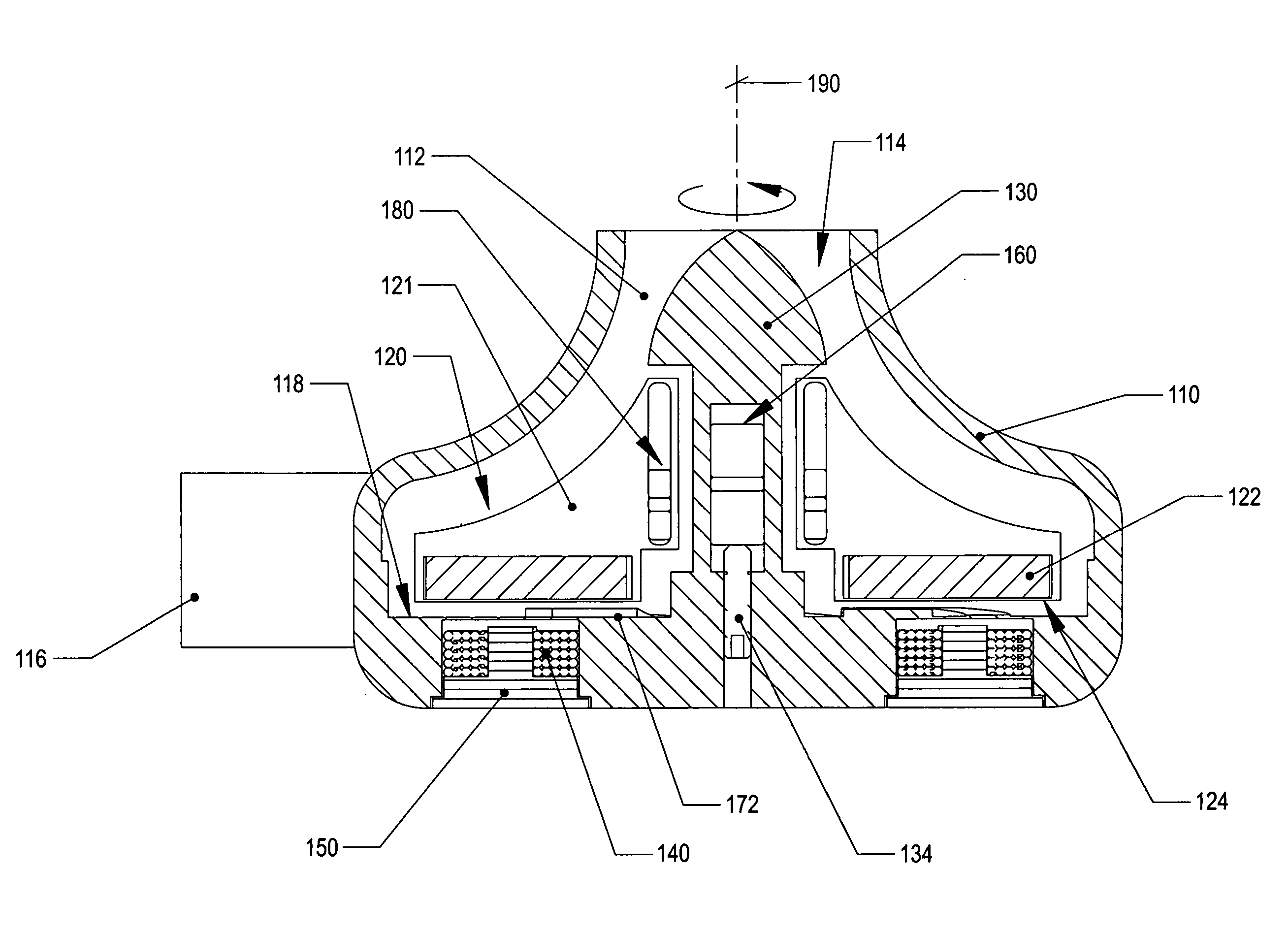
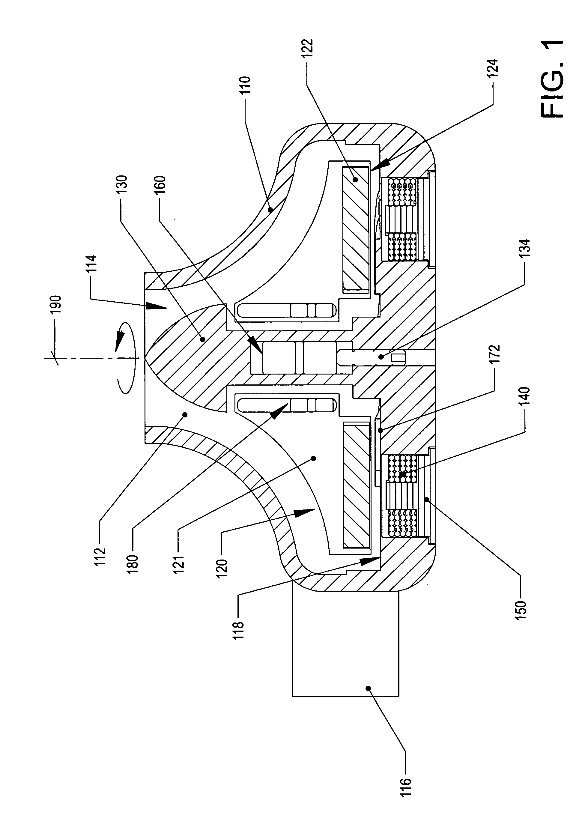
[0026]FIG. 1 illustrates one embodiment of a centrifugal blood pump. The pump comprises a housing 110 defining a pumping chamber 112 between an inlet 114 and an outlet 116. Within the pumping chamber, a rotor 120 rotates about a spindle 130 protruding from a base of the pump housing. The rotor further comprises a bladed portion defining an impeller that provides the fluid moving surfaces. The impeller comprises one or more blades 121 that move fluids when the impeller rotates.

[0027] The terms “rotor” and “impeller” may be used interchangeably in some contexts. For example, when the rotor is rotating, the blade portion of the rotor is inherently rotating such that reference to rotation of either the impeller or the rotor is sufficient to describe both. When necessary, however, the term “non-bladed portion of the rotor” or “rotor excluding the impeller” may be used to specifically identify portions of the rotor other than the blades. Each blade of the rotor may separately be referred...


PUM


Abstract

Various “contactless” bearing mechanisms including hydrodynamic, hydrostatic, and magnetic bearings are provided for a rotary pump as alternatives to mechanical contact bearings. These design features may be combined. In one embodiment, a pump housing has a spindle extending from a wall of the pump housing into a pumping chamber defined by the pump housing. The spindle has a stepped portion adjacent the wall. In one embodiment, the stepped portion is defined by a change in spindle diameter. The lack of mechanical contact bearings enables longer life pump operation and less damage to working fluids such as blood.

Description

CROSS-REFERENCE TO RELATED APPLICATIONS [0001] This application claims the benefit of U.S. Provisional Application No. 60 / 504,233 of Wampler, et al. filed Sep. 18, 2003.FIELD OF THE INVENTION [0002] This invention relates to the field of rotary pumps. In particular, this invention is drawn to bearings for various rotor and impeller architectures. BACKGROUND OF THE INVENTION [0003] Typical rotary pumps utilize an impeller wherein the movement of the impeller is constrained in five degrees of freedom (two angular, three translational) by mechanical contact bearings. Some working fluids may be damaged by the mechanical contact bearings. Blood pumped through pumps with contact bearings can experience hemolysis, i.e., damage to blood cells. In general, a hydraulically efficient and power efficient pump that can handle delicate working fluids such as blood is desirable for some applications. [0004] U.S. Pat. No. 6,234,772 B1 of Wampler, et al., (“Wampler”) describes a centrifugal blood pu...

Claims


Application Information

Patent Timeline
Patent Type & Authority Applications(United States)
IPC IPC(8): F04F99/00A61M60/232A61M60/422A61M60/81A61M60/822A61M60/824F04B17/00F04B17/03F04B35/04
CPCA61M1/101F04D13/0666F04D29/047F04D29/048F16C32/044F16C2316/18A61M1/1036F04D29/0413A61M1/1013F04D29/0473A61M1/1015A61M1/1017A61M1/1031Y10S415/90A61M60/824A61M60/422A61M60/419A61M60/148A61M60/81A61M60/232A61M60/822F04D1/00F04D13/06F04D29/22F04D29/426F04D29/628F04D29/043
Inventor WAMPLER, RICHARD K.LANCISI, DAVID M.
Owner TC1 LLC
Why Eureka
Try Eureka