

Cross-connector means for electrical junction boxes and the like
- Summary
- Abstract
- Description
- Claims
- Application Information
AI Technical Summary
Benefits of technology
Problems solved by technology
Method used
Image

Examples
Embodiment Construction
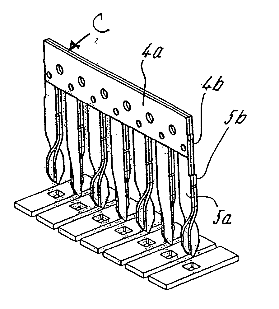
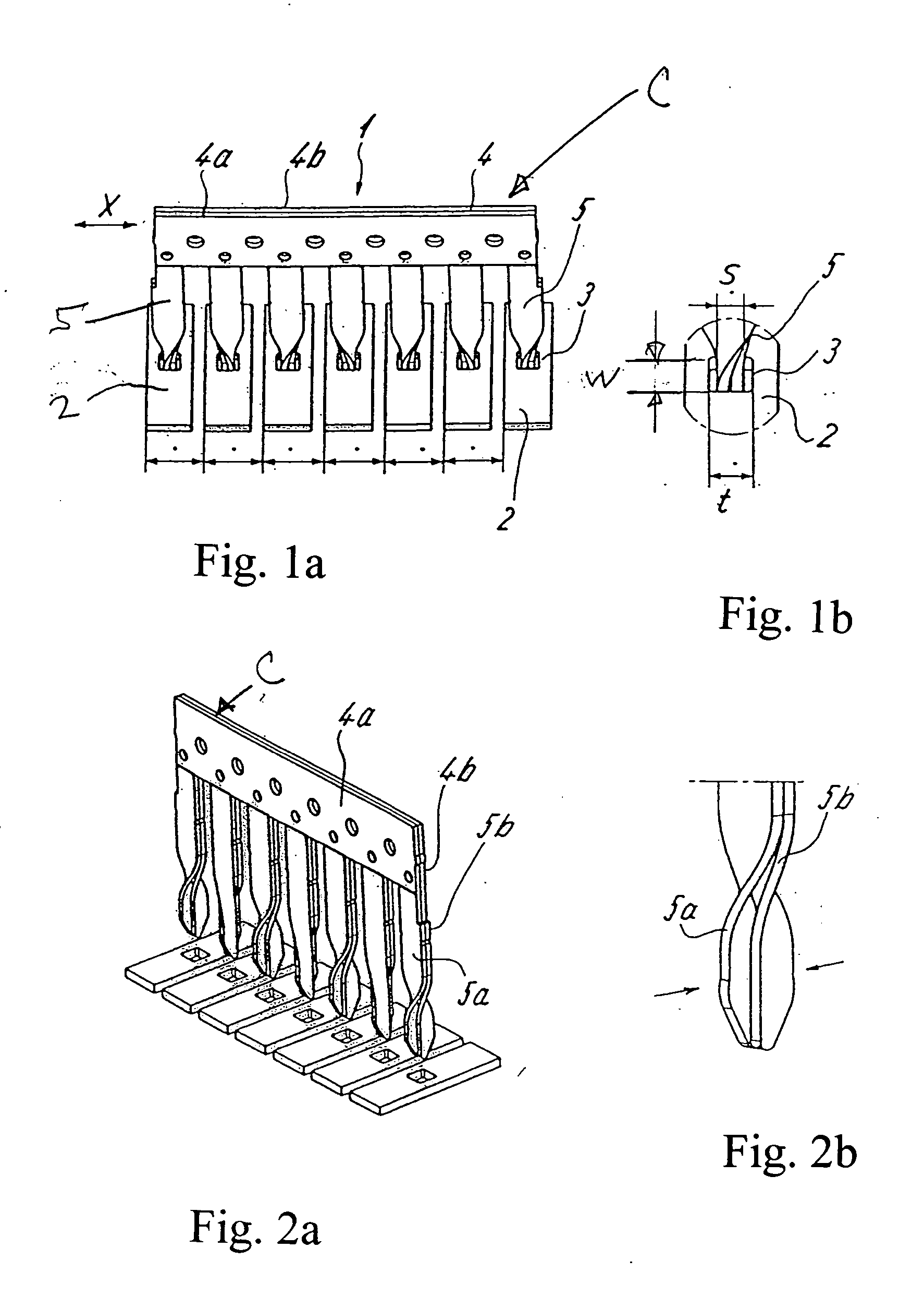
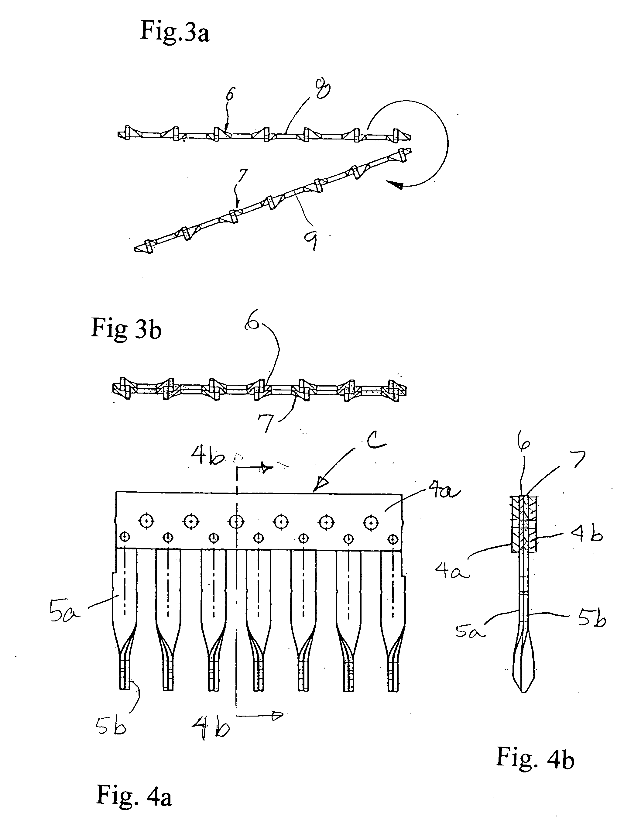
[0018] Referring first more particularly to FIGS. 1a-2b, the connector assembly 1 of the present invention includes a comb-like member C that is adapted for connection with a plurality of parallel bus bars 2 each containing a connecting opening 3. The cross-connector C includes a body portion 4 that is parallel to the plane of the bus bars 3 and extends in spaced relation above and transversely of the bus bars. Extending downwardly from the comb body portion 4 are a plurality of contact fingers 5, having twisted lower ends that extend within the bus bar openings 3, respectively. The contact fingers have upper ends that are connected with the connector body portion 4, lower ends that are twisted about the longitudinal axes of the contact fingers, respectively. The contact members 5 are preferably formed from a pair of contiguous separate resilient conductive metal sheets 5a and 5b, respectively, whereby the twisted end portions of each contact finger 5 are resiliently separated, as b...
PUM
 Abstract
Description
Claims
Application Information