Error-detecting encoding and decoding apparatus and dividing apparatus

a technology of encoding and decoding apparatus and dividing apparatus, which is applied in the direction of coding, code conversion, instruments, etc., can solve the problems of inability to resend control, marked decline in data transmission rate, and delay of one packet length, so as to shorten the time needed for crc calculation

Inactive Publication Date: 2005-05-05
FUJITSU LTD
View PDF10 Cites 85 Cited by
  • Summary
  • Abstract
  • Description
  • Claims
  • Application Information

AI Technical Summary

Benefits of technology

[0037] Accordingly, an object of the present invention is to shorten the time needed for CRC calculation.

Problems solved by technology

In this case also there is a delay of one packet length brought about merely by CRC error detection.
If resend control also is taken into account, there will be a marked decline in the data transmission rate since generating a resend-request signal takes time.
Here resend control is not realistic.

Method used


Image

  • Error-detecting encoding and decoding apparatus and dividing apparatus
  • Error-detecting encoding and decoding apparatus and dividing apparatus
  • Error-detecting encoding and decoding apparatus and dividing apparatus

Examples


first embodiment

(B) First Embodiment

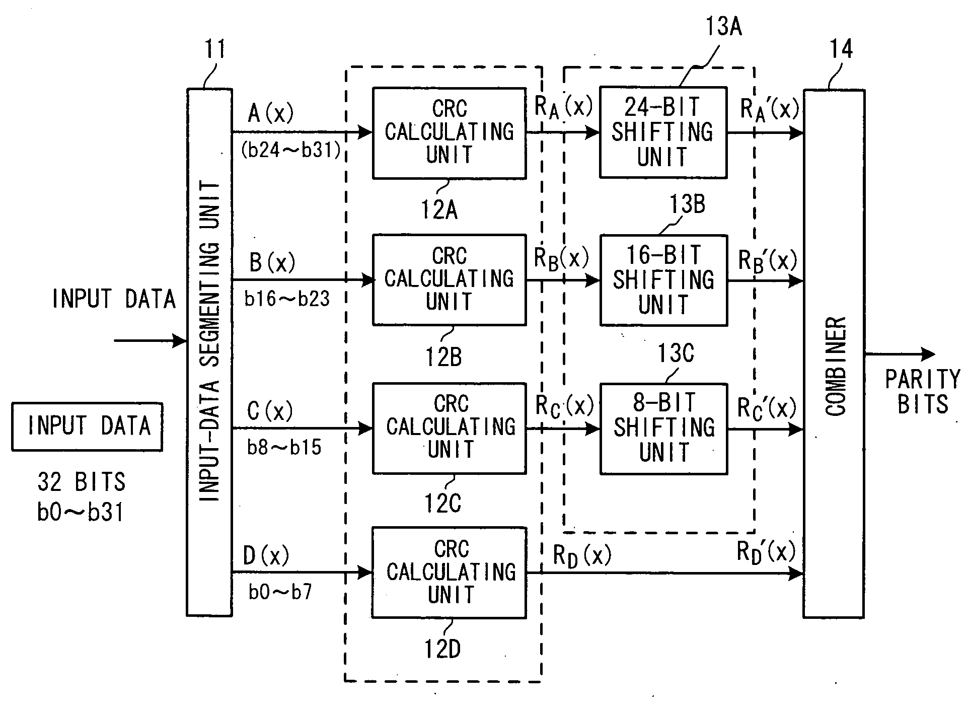
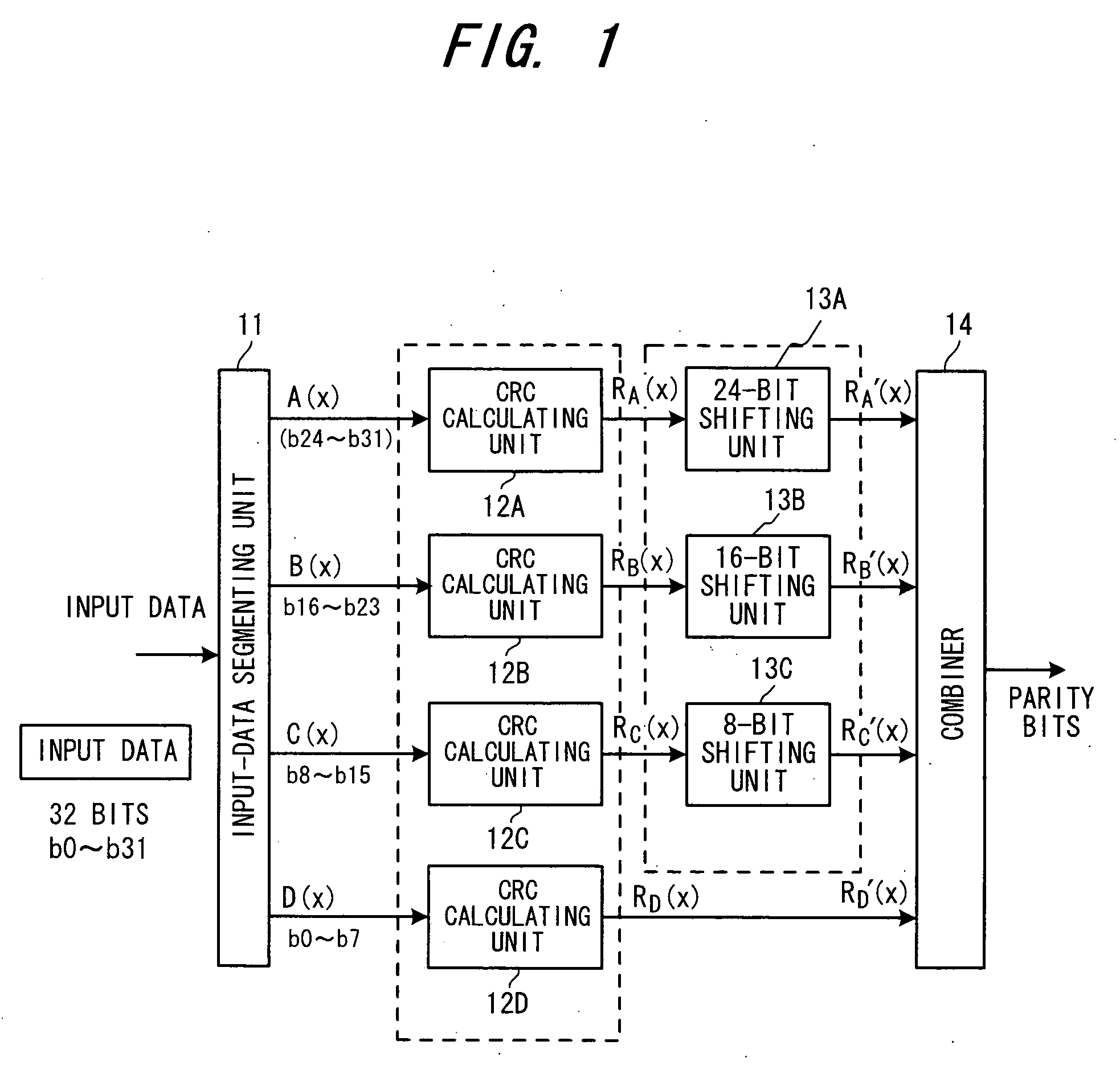
[0157]FIG. 30 is a diagram illustrating the structure of an error-detecting encoder according to a first embodiment. This is for a case where CRC parity of a 32-bit data string x1 to x31 is generated by the generator polynomial G(x)=x16+x12+x5+1. Components in FIG. 30 identical with those shown in FIG. 1 are designated by like reference characters. Further, it is assumed that 32-bit input data is segmented into strings x0 to x7, x8 to x15, x16 to x23, x24 to x31 of eight bits each and is expressed by

x24A(x)+x16B(x)+x8(x)+D(x)

[0158] Assume that the initial value in the shift register SR in all of the CRC calculating units 12A to 12D is “0”. A data segmenting unit (not shown) segments the 32-bit data string into strings x0 to x7, x8 to x15 x16 to x23, x24 to x31 of eight bits each and input these strings to respective ones of the CRC calculating units.

[0159] The bits x31 to x24 are input to the shift register of the CRC calculating unit 12A from the higher order...

second embodiment

(C) Second Embodiment

[0164]FIG. 31 is a diagram illustrating the structure of an error-detecting encoder according to a second embodiment. Components in FIG. 31 identical with those shown in FIG. 15 are designated by like reference characters. Here 16-bit CRC parity has been appended to the lower order side of 32-bit input data. This CRC parity has been generated using the generator polynomial G(x)=x16+x12+x5+1 and appended to the input data string. Accordingly, the error-detecting decoder detects whether the information bits of 32 bits and the 16-bit CRC parity are correct using this generator polynomial G(x)=x16+x12+x5+1.

[0165] Assume that the initial value in the shift register SR in all of the CRC calculating units 22A to 22D is “0”. A data segmenting unit (not shown) separates the 48-bit data string into 16-bit CRC parity x0 to x15 on the lower order side and 32-bit input data x16 to x47 on the higher order side, segments the 32-bit input data into data strings x16 to x23, x24...

third embodiment

(C) Third Embodiment

[0171]FIG. 32 is a diagram illustrating the structure of an error-detecting encoder according to a third embodiment. Components in FIG. 32 identical with those shown in FIG. 21 are designated by like reference characters. In FIG. 32, 16-bit CRC parity has been appended to the lower order side of 32-bit input data. This CRC parity has been generated using the generator polynomial G(x)=x16+x12+x5+1 and appended to the input data string. Accordingly, the error-detecting decoder detects whether the information bits of 32 bits and the 16-bit CRC parity are correct using this generator polynomial G(x)=x16+x12+x5+1.

[0172] The 48-bit data string is segmented into data strings x0 to x7, x8 to x15, x16 to x23, x24 to x31, x32 to x39, x40 to x47 of eight bits each and is expressed by the following polynomial:

x40A(x)+x32B(x)+x24C(x)+x16D(x)+x8E(x)+F(x)

[0173] Assume that the initial value in the shift register SR in all of the CRC calculating units 32A to 32F is “0”. A dat...


PUM


Abstract

Disclosed are an error-detecting encoding apparatus for creating parity bits by error-detecting encoding processing, appending the parity bits to an input data string and encoding the data string, and an error-detecting decoding apparatus for detecting error using these parity bits. Data segmenting means segments an input data string, which is to undergo error-detecting encoding, into a plurality of sub-data strings, dividing means divides the segmented sub-data strings by a polynomial, which is for generating an error-detecting code, and calculates remainders, converting means applies conversion processing, which conforms to a segmentation position of the sub-data strings, to the remainders on a per-remainder basis, and combining means combines converted values, which have been obtained by the conversion processing, and outputs parity bits. An encoder appends this parity to a data string, and a decoder detects error using this parity.

Description

BACKGROUND OF THE INVENTION [0001] This invention relates to an error-detecting encoding and decoding apparatus and to a dividing apparatus. More particularly, the invention relates to an error-detecting encoding apparatus for generating parity bits for detecting error in an input data string and appending the parity bits to the data string, an error-detecting decoding apparatus for applying error-detecting processing to an input data string to which parity bits have been appended and detecting error in the input data string, and a dividing apparatus that can be used in this error-detecting encoding and decoding apparatus. [0002] An error-detecting code is applied in a system in which it is required that data be transmitted without error when data communication is carried out, as in the case of mobile communications, facsimile machines and cash dispensers at banks, etc., or in a system in which it is required that data be read out without error when a large quantity of data is store...

Claims


Application Information

Patent Timeline
Patent Type & Authority Applications(United States)
IPC IPC(8): G06F11/00H03M13/00H03M13/09H04L1/00
CPCH03M13/091H03M13/093H04L1/1829H04L1/0061H04L1/0043
Inventor OBUCHI, KAZUHISAYANO, TETSUYANAKAMURA, TAKAHARU
Owner FUJITSU LTD
Why Eureka
Try Eureka