Umbrella structure

a technology of umbrellas and tubes, applied in the field of umbrella structures, can solve the problems inability to securely stretch umbrellas, etc., and achieve the effects of reducing the volume of umbrellas, preventing damage and deformation of inner tubes, and strengthening umbrellas

Active Publication Date: 2005-05-12
SU PING TUNG
View PDF6 Cites 29 Cited by
  • Summary
  • Abstract
  • Description
  • Claims
  • Application Information

AI Technical Summary

Problems solved by technology

Using the aforesaid structure, a drawback as being incapable of securely stretching the umbrella due to reduced volume of the umbrella is solved.

Method used


Image

  • Umbrella structure
  • Umbrella structure
  • Umbrella structure

Examples


Embodiment Construction

[0037] To better understand the effects, structure and characteristics of the invention, detailed descriptions of preferred embodiments shall be given with the accompanying drawings below.

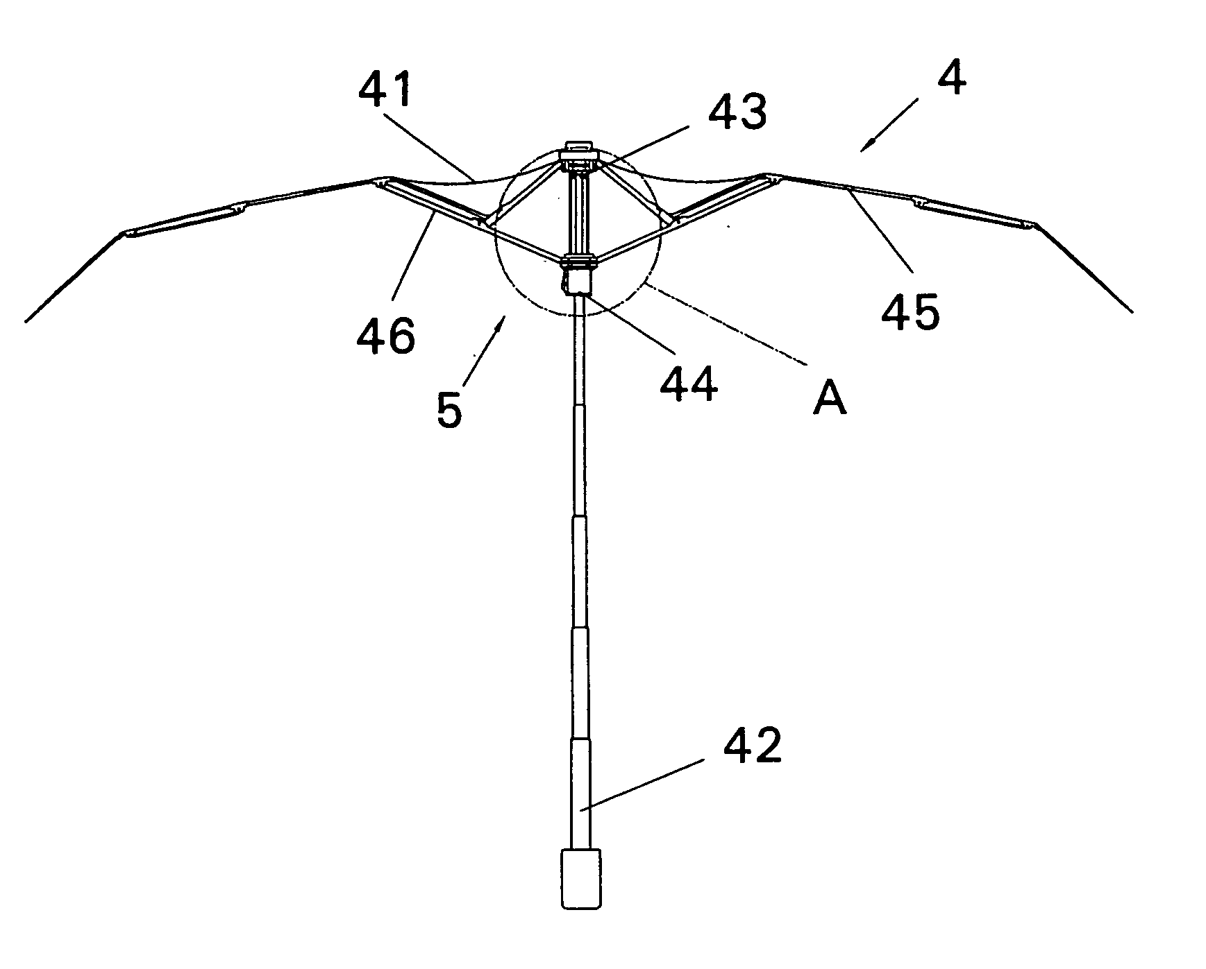
[0038] Referring to FIGS. 8 and 8A, an umbrella 4 according to the invention comprises a cover 41, a shaft 42, a notch 43, a runner 44, main ribs 45 and stretchers 46. Around the notch 43 is a plurality of pivotally disposed main ribs 45 for supporting the cover 41. Around the runner 44 is a plurality of pivotally disposed stretchers 45 for supporting the ribs 45. One side of the runner 44 is provided with a fastening device 5 having a protruding button 51. The shaft 42 is devised as a multi-sectional structure and is fastened at a center of the notch 43. The notch 43 is extended downward to form a fixing portion 431. The fixing portion 431 has one end thereof disposed with a protruding loop section 435, and an appropriate position thereof disposed with a fastening orifice 432 for corresponding wi...


PUM


Abstract

An umbrella structure includes a cover, a shaft, a notch, a runner, main ribs and stretchers. The notch is extended downward to form a fixing portion. The fixing portion has one end disposed with a protruding loop section, and an appropriate position disposed with a fastening orifice for corresponding with the protruding button. The runner is accommodated at the fixing portion, and is capable of up-and-down sliding movements at the fixing portion. When stretching the umbrella, the protruding button at the fastening device is steadily locked at the fastening orifice at the fixing portion to smoothly stretch the umbrella. When collapsing the umbrella, the shaft is stored in the fixing portion to prevent the shaft from damages and deformations by offering the shaft with appropriate protection. Using the aforesaid structure, a drawback as being incapable of securely stretching the umbrella due to a reduced volume of the umbrella is solved.

Description

BACKGROUND OF THE INVENTION [0001] (a) Field of the Invention [0002] The invention relates to an umbrella structure, and more particularly, to an umbrella structure, which overcomes drawbacks in the existing state of the art which is incapable of securely locking the fastening orifice after reducing the volume of the umbrella. [0003] (b) Description of the Prior Art [0004] With reference to FIGS. 1 and 1A, a prior umbrella comprises a cover 11, a shaft 12, a notch 13, a runner 14, main ribs 15 and stretchers 16. Around the notch 13 is a plurality of pivotally disposed main ribs 15 for supporting the cover 11, whereas around the runner 14 is a plurality of pivotally disposed stretchers 16 for supporting the main ribs 15. The shaft 12 is in a two-sectional or three-sectional form, and has a top end thereof fixed to the notch 13. The notch 13 is fastened with an inner tube 122, which has a rectangular fastening orifice 121 at an appropriate position for setting free a fastening button ...

Claims


Application Information

Patent Timeline
Patent Type & Authority Applications(United States)
IPC IPC(8): A45B19/00
CPCA45B2009/007A45B19/00A45B25/08A45B25/10
Inventor SU, PING-TUNG
Owner SU PING TUNG
Why Eureka
Try Eureka