
Apparatus and method for exchanging vehicular fluids

Inactive Publication Date: 2005-05-12
ROUNDS TODD M +2
View PDF58 Cites 12 Cited by
  • Summary
  • Abstract
  • Description
  • Claims
  • Application Information

AI Technical Summary

Problems solved by technology

If contaminants, such as dirt, oil sludge, gum, varnish, burned oil, deposits from worn parts, residues of transmission fluid additives, etc., are not properly flushed from the automatic transmission system, they can cause slow and hesitant acceleration, rough or erratic shifting, incorrect shift points, excessive creep and abnormal vibration when gears are shifted, gear position slippage or lock up, premature transmission fluid burn-out causing excessive fluid consumption and overheating, premature component wear.
If these problems are not resolved in a timely manner, an expensive transmission overhaul may be required.
It is known, however, that when employing this method more than half of the used and contaminated transmission fluid remains in the transmission and the various related components operative therewith, including the clutch actuators, control valves, pump(s), transmission fluid cooler and connecting conduits, and the torque converter.
Alternatively, the vehicle engine can be run with the transmission in “neutral” or “park.” The latter process is less efficient than the former with respect to the quantity of used fluid replaced with new fluid.
Use of the force / pressure of the vehicle's used fluid to infuse new fluid into the transmission system can result in a slow exchange process, as the exchange duration depends on the pressure of the used fluid as it exits the vehicle and the mechanism by which the pressurized fluid flow operates the flush mechanism.
Thus when employing such a machine with a low-pressure vehicle, the fluid exchange process may require 30 to 40 minutes.
These pressures may be excessive for certain existing fluid flow machines, and can damage machine components.
Additionally, the prior art machines may not be able to supply a sufficiently high pressure to the new fluid as it is infused into the vehicle.
Another disadvantage encountered in the prior art fluid exchange machines is caused by the expected viscosity differential between the new and the used fluids during the exchange process.
Machine inefficiencies will arise as the incoming lower viscosity used fluid attempts to force the higher viscosity new fluid into the vehicle, as the pressure supplied by the old fluid to force the new fluid into the vehicle may not be sufficient given the higher viscosity of the new fluid.
There is considerable uncertainty with these prior art machines that the rate of new fluid delivery substantially matches the rate of old fluid drainage from the transmission under service, possibly creating a situation where the transmission may be operating with insufficient fluid and damaging the system.

Method used

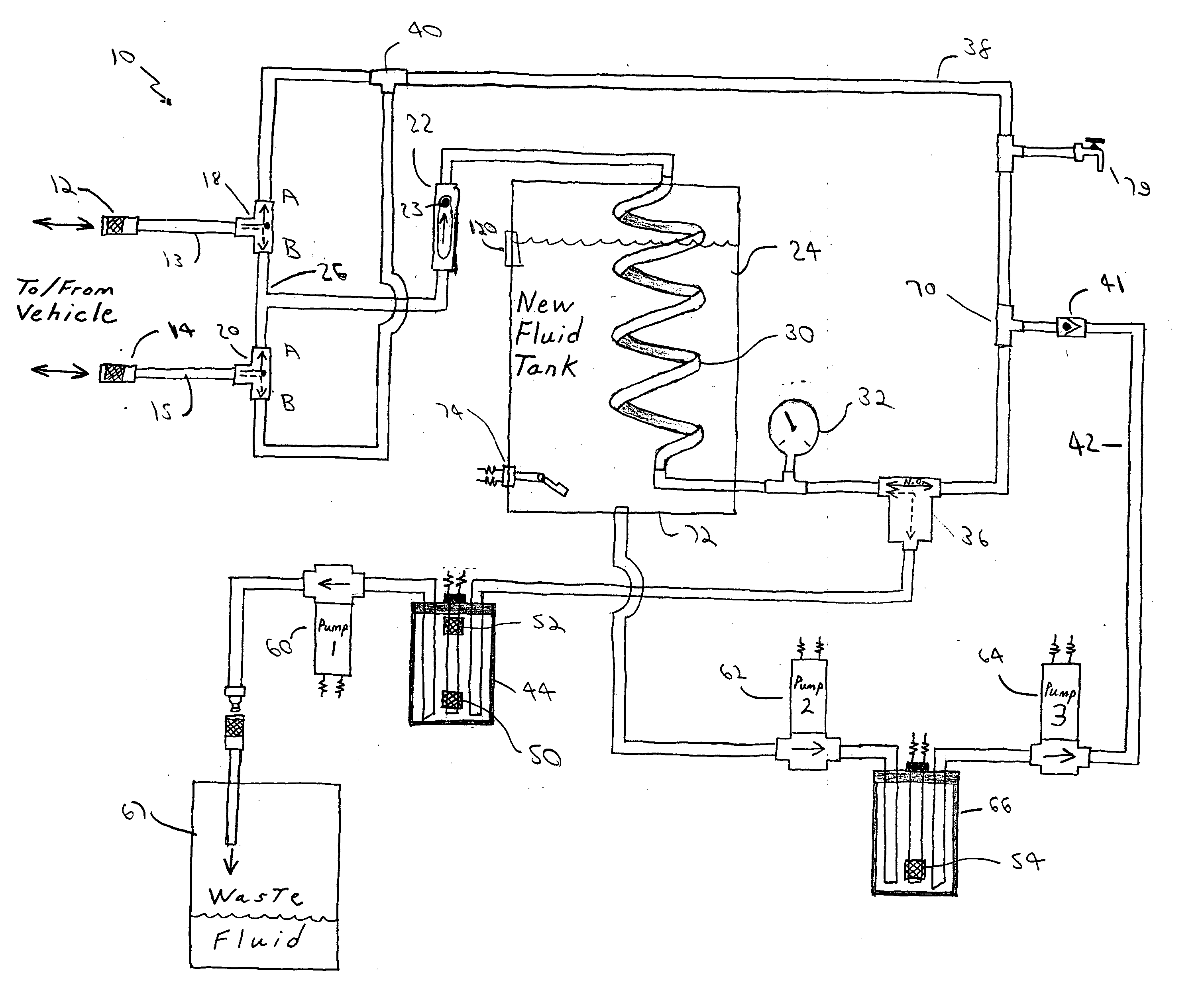
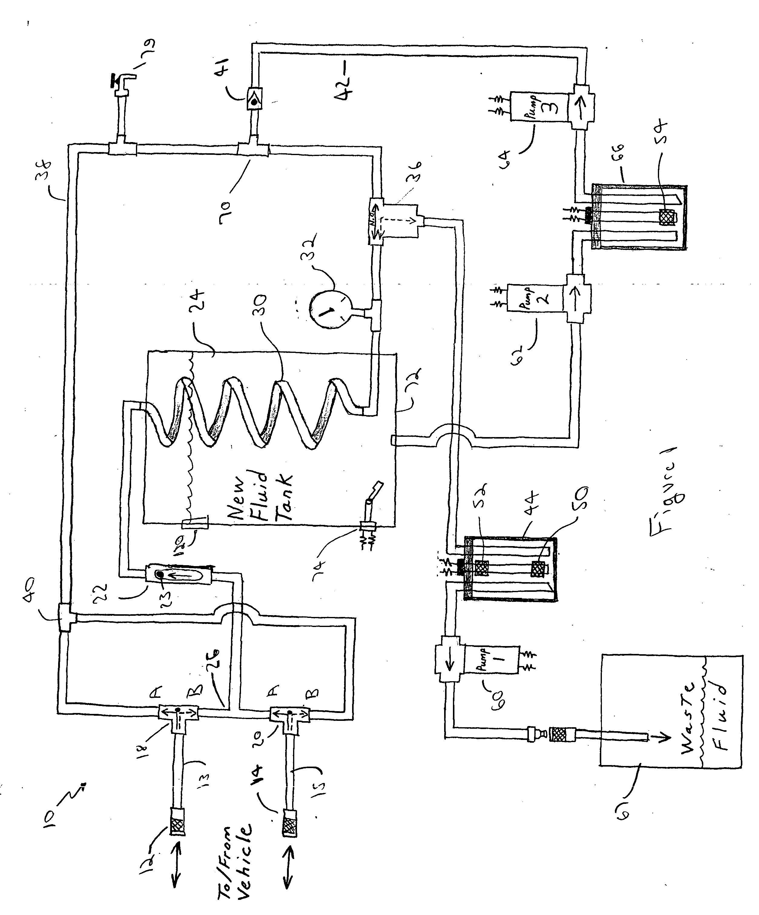
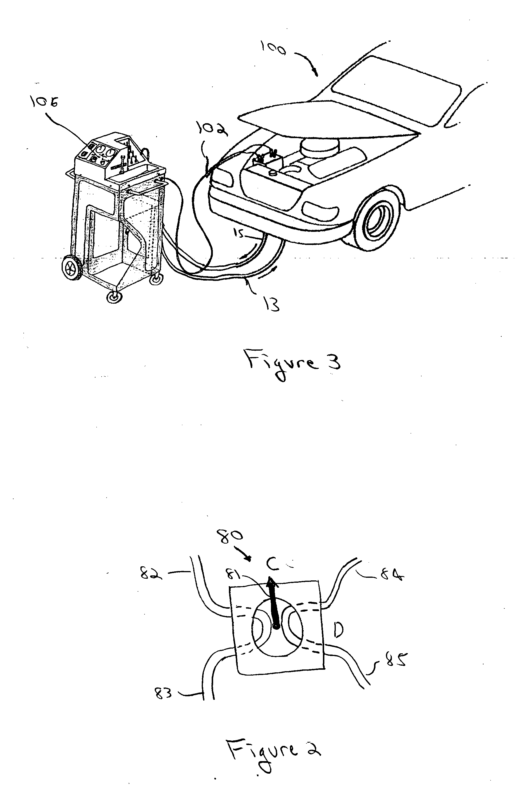

Image

  • Apparatus and method for exchanging vehicular fluids
  • Apparatus and method for exchanging vehicular fluids
  • Apparatus and method for exchanging vehicular fluids

Examples


Embodiment Construction

[0023] Before describing in detail the particular fluid replacement machine and a method for replacing fluid according to the teachings of the present invention, it should be observed that the present invention resides primarily in a novel and non-obvious combination of elements and method steps. Accordingly, the elements have been represented by conventional elements in the drawings, showing only those specific details that are pertinent to the present invention, so as not to obscure the disclosure with structural details that will be readily apparent to those skilled in the art having the benefit of the description herein.

[0024] One advantage of a machine and process according to the teachings of the present invention is use of the volume of used fluid evacuated from the system to control the exchange process. The use of pressure / force of the used fluid from the vehicle, as disclosed by the prior art, is not employed. As stated above, the exchange time is dictated by the speed at...


PUM


Abstract

A method and apparatus for exchanging used fluid in a system with new fluid. Used fluid is withdrawn from the system and stored in a first chamber. In response to the used fluid in the first chamber a first and a second pump are activated. The first pump withdraws the used fluid from the first chamber into a waste tank. The second pump draws new fluid from a new fluid tank for infusion into the vehicle. In an alternative embodiment the second pump draws new fluid from the new fluid tank into a second chamber. New fluid in the second chamber activates a third pump for withdrawing new fluid from the second chamber and infusing the new fluid into the system.

Description

FIELD OF THE INVENTION [0001] The present invention relates to an apparatus and method for exchanging vehicular fluids, and more specifically to an apparatus and method for exchanging vehicular fluids according to fluid volume. BACKGROUND OF THE INVENTION [0002] A vehicular transmission system transfers engine power to the vehicle drive train, allowing the engine to operate in a narrow speed range, while providing a wide range of output speeds and torques to the drive train. This power transfer is accomplished within the transmission, in which a plurality of gears automatically select the proper gear ratio, in conjunction with the position of the user operated transmission gear shift, based on the vehicle's speed and torque demand. [0003] Two other components associated with the transmission system include the torque converter and the gear or fluid pump. The converter is mounted to the engine flywheel (which is in turn mounted on the engine drive shaft) to provide fluid coupling bet...

Claims


Application Information

Patent Timeline
IPC IPC(8): B65B31/04F01M11/04
CPCF01M11/0458
Inventor ROUNDS, TODD M.HEILIGER, JEFF T.MONJE, MICHAEL A.
Owner ROUNDS TODD M
Learn More