
Cord taking-up and releasing device

a technology of which is applied in the direction of web handling, tightening, thin material handling, etc., can solve the problems that conventional taking-up and releasing devices are not able to effectively release and rewind an overlong cord or similar linear material, and the effectiveness of such structures is frequently subject to subject matter, so as to achieve convenient operation and not affect the effect of functional

Inactive Publication Date: 2005-05-12
HUANG WEN SHENG
View PDF7 Cites 142 Cited by
  • Summary
  • Abstract
  • Description
  • Claims
  • Application Information

AI Technical Summary

Benefits of technology

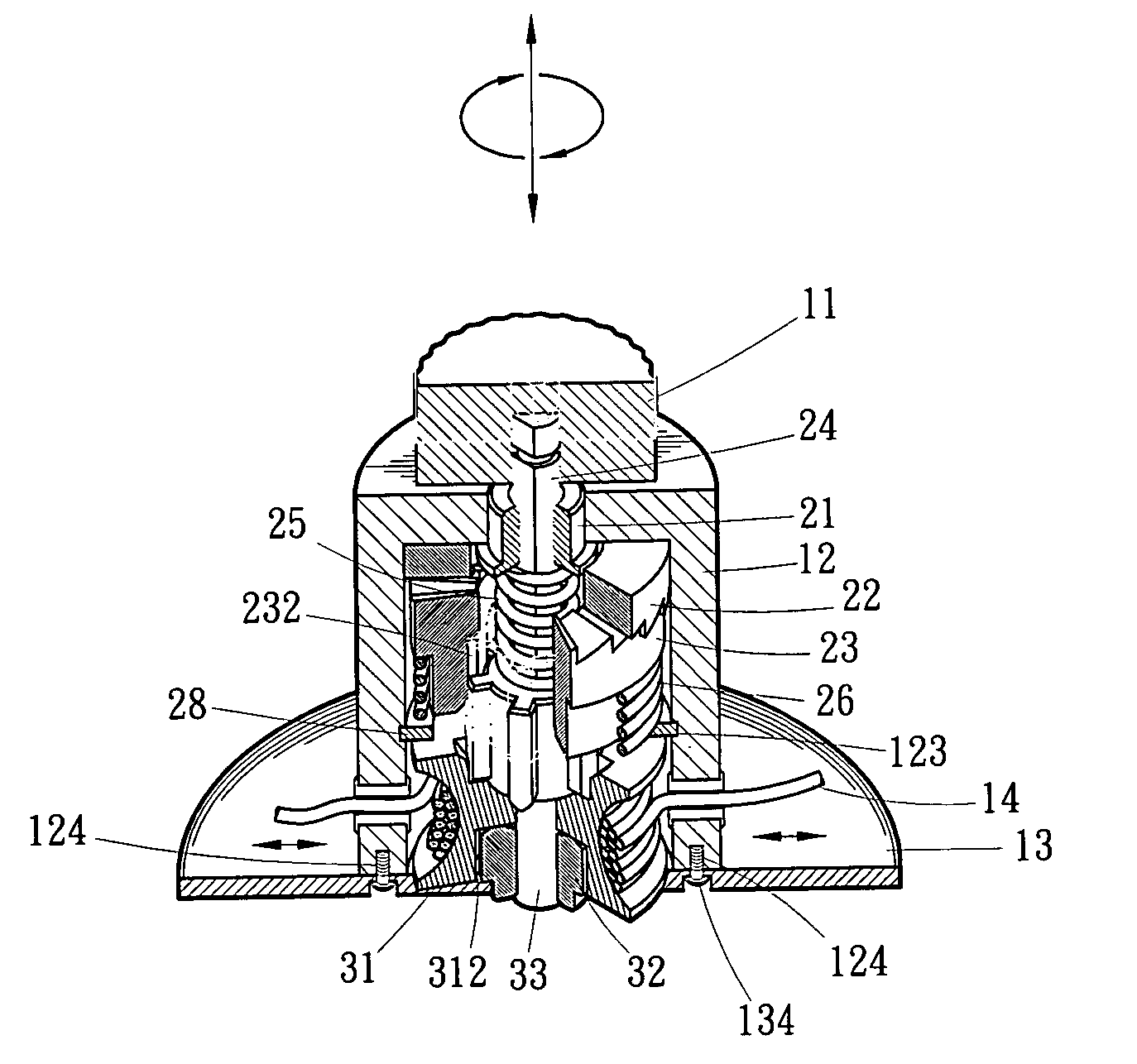
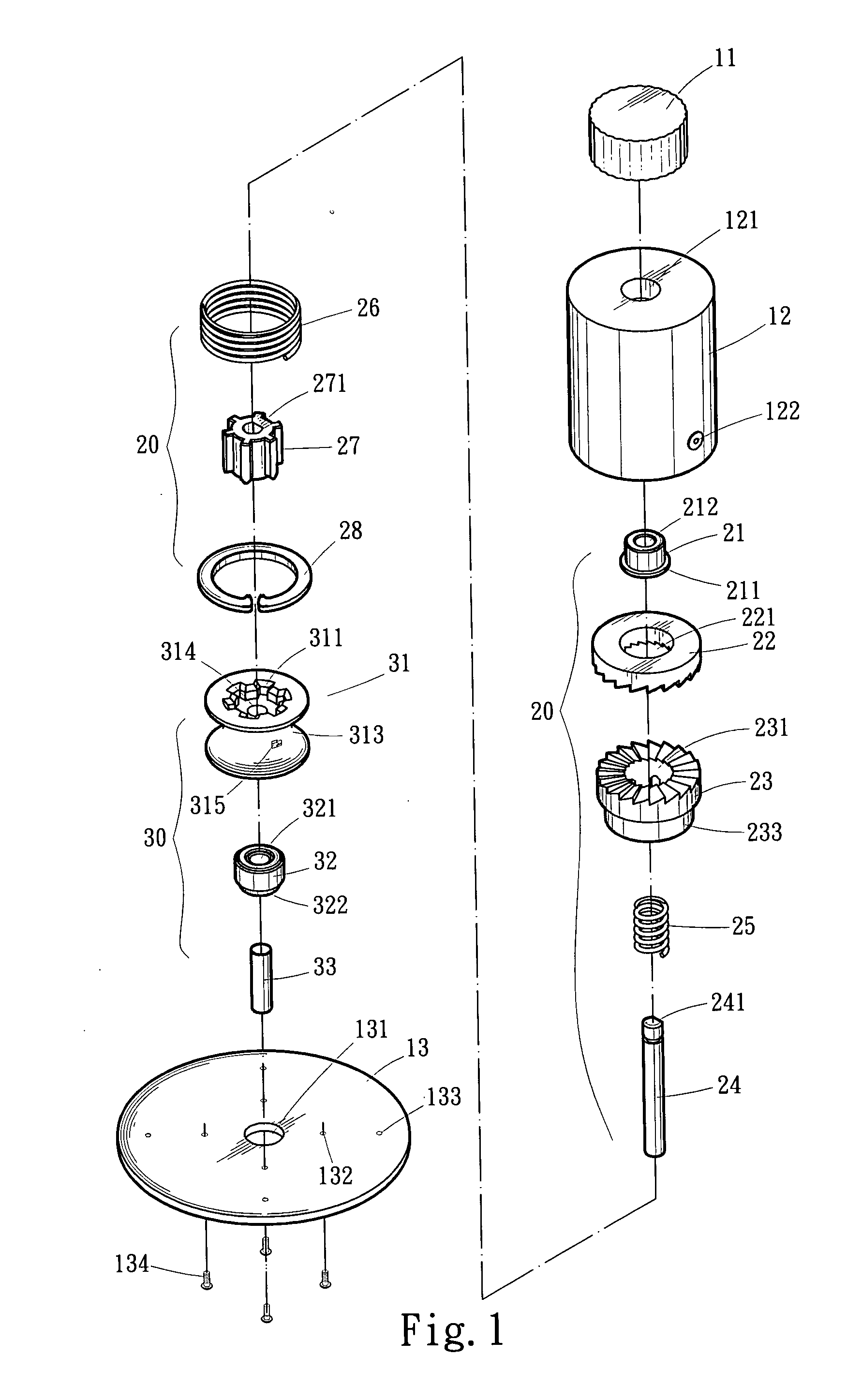
[0017] The first shaft is upward extended through shaft holes of the lower ratchet, the upper ratchet, and the upper shaft collar to project from the housing via the first guide hole and connect to the turning knob. When the turning knob is turned clockwise, the first shaft, the retaining gear, and the reel are brought to turn along with the lower ratchet, so that the cord tied to the reel is wound around the reel and tightened. Reversely, when the turning knob is turned counterclockwise, the immovable upper ratchet prevents the lower ratchet and other parts coupled therewith from rotating reversely. To loosen or release the cord, simply upward pull the turning knob for the first shaft and the retaining gear to synchronously slide upward and disengage a lower end of the retaining gear from axial guide slots at an upper end of the reel, so that the reel is allowed to freely rotate reversely to release the cord, and the cord in a loosened state could be pulled outward via the two spaced holes on the housing.
[0018] With the above arrangements, the cord taking-up and releasing device of the present invention is more easily operable and not functionally affected by the length of the cord to be wound around or released from the reel.

Problems solved by technology

The effectiveness of such structure is frequently subject to the length of the spiral spring.
That is, the conventional taking-up and releasing devices are not able to effectively release and rewind an overlong cord or similar linear material.

Method used


Image

  • Cord taking-up and releasing device
  • Cord taking-up and releasing device
  • Cord taking-up and releasing device

Examples


Embodiment Construction

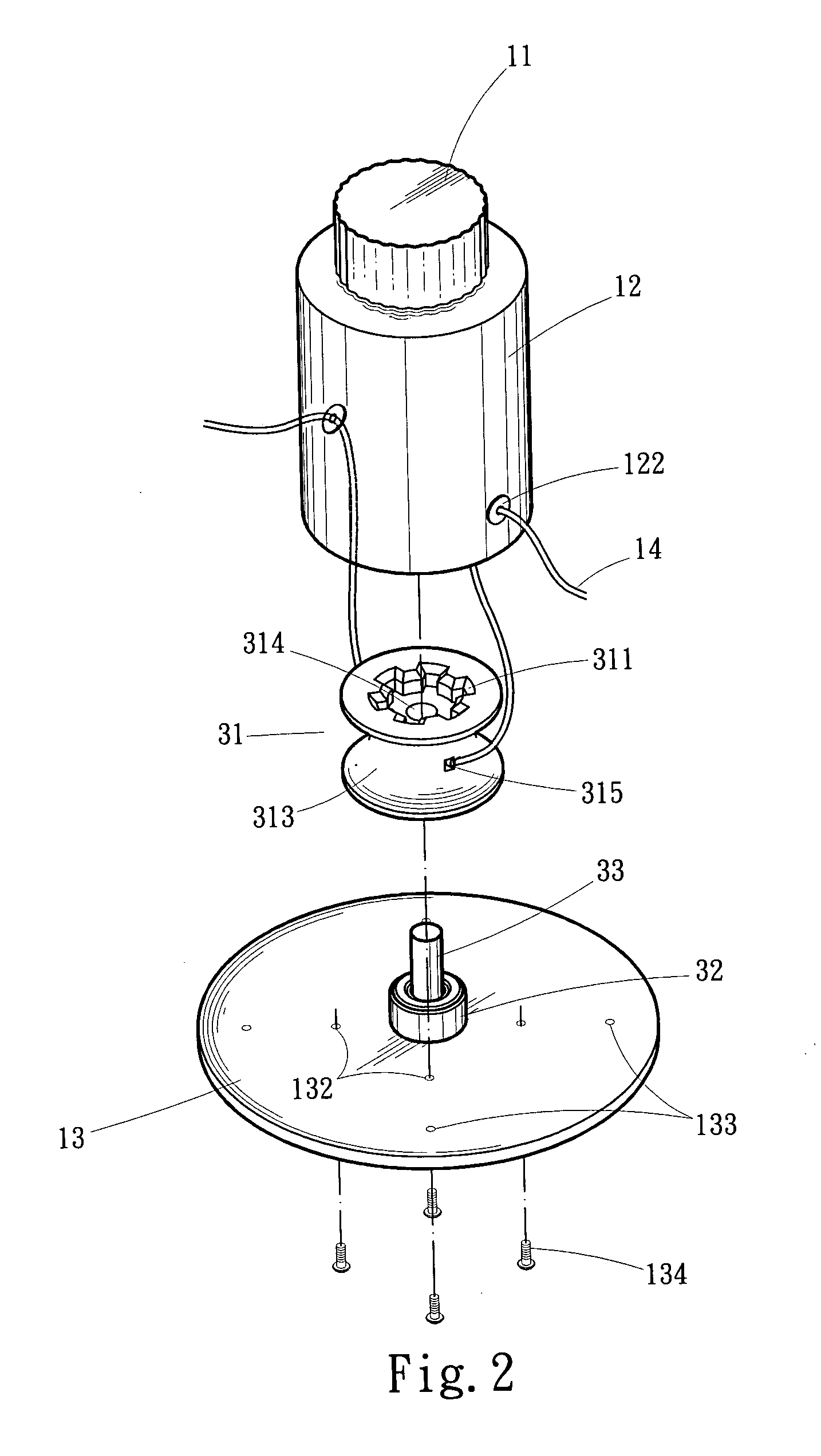
[0026] Please refer to FIGS. 1 to 3 in which a cord taking-up and releasing device according to the present invention is shown. As can be clearly seen from the drawings, the cord taking-up and releasing device of the present invention mainly includes a main body 10 consisting of a turning knob 11, a housing 12, and a seat 13 (see FIG. 3); a taking-up and releasing unit 20 received in the housing 12 of the main body 10 and including an upper shaft collar 21, an upper ratchet 22, a lower ratchet 23, a first shaft 24, inner and outer elastic elements 25, 26, a retaining gear 27, and a C-shaped retaining ring 28; and a cord-winding unit 30 mounted on the seat 13 of the main body 10 and including a reel 31, a lower shaft collar 32, and a second shaft 33.

[0027] The housing 12 of the main body 10 is provided at a top with a first guide hole 121, near a lower end with two diametrically opposite or circumferentially properly spaced holes 122, on an inner wall surface with an annular groove ...


PUM


Abstract

A cord taking-up and releasing device includes a main body consisting of a housing, a turning knob on a top of the housing, and a seat below the housing; a taking-up and releasing unit received in the housing and including a first shaft connected at an upper end to the turning knob and at a lower end to a retaining gear; and a cord-winding unit mounted on the seat of the main body and including a reel having an upper end engaged with the retaining gear, a lower end rotatably connected to a second shaft, and a middle portion, to which two ends of a cord are tied. Through manipulation of the turning knob, the taking-up and releasing unit brings the cord-winding unit to quickly take up or release the cord tied to the reel without being affected by the length of the cord wound around the reel.

Description

FIELD OF THE INVENTION [0001] The present invention relates to a cord taking-up and releasing device, and more particularly to a novel cord taking-up and releasing device that enables quick and safe taking-up and releasing of a cord tied thereto. BACKGROUND OF THE INVENTION [0002] Most of the currently available cord taking-up and releasing devices typically include a housing, a ratchet, a spiral elastic element, and a locking gear. A lot of invention and new utility model patents have disclosed cord taking-up and releasing devices having the above-mentioned basic structure in an attempt to improve the function and industrial value of the devices. [0003] Taiwanese Patent Publication No. 509017 discloses an automatic shoulder belt rewinder, which mainly includes a case, a cover plate, a ratchet, and a locking gear. The case defines an internal receiving space, and has a slot provided at an upper end of one side thereof. The cover plate is closed to an open side of the case. The ratch...

Claims


Application Information

Patent Timeline
IPC IPC(8): A43C7/00A43C7/08A44B99/00A45C13/00B65H75/30B65H75/38B65H75/44
CPCA43C7/00B65H2701/537B65H75/4431A43C11/165
Inventor HUANG, WEN-SHENG
Owner HUANG WEN SHENG
Learn More