System and method for displaying material characteristic information

a technology of characteristic information and system, applied in the direction of material analysis using wave/particle radiation, 2d-image generation, instruments, etc., can solve the problems of unfavorable or tragic consequences, loss of human life or other tragic, calculation of stress error present in measuring stress, etc., to achieve the effect of easy determination

Active Publication Date: 2005-05-12
PROTO MANUFACTURING LTD
View PDF25 Cites 76 Cited by
  • Summary
  • Abstract
  • Description
  • Claims
  • Application Information

AI Technical Summary

Benefits of technology

[0028] The evaluation guide is also beneficial because a viewer can easily determine how test measurement resultants compare against the evaluation guide. Again, this determination can easily be made and corrective action quickly taken before the part under test fails. In this regard, and as has been discussed above, the operator can view the evaluation guide in graphical form and compare the guide to test measurement resultants as the measurement values are taken. If the comparison between the guide and the values indicates nonconformance, then the operator can take appropriate action.
[0029] The embodiments are useful to effect various economical, reliable, relatively intuitive, and relatively scalable solutions to at least some of the various concerns and issues noted herein.

Problems solved by technology

The failure of fatigue-limited components in various types of systems often leads to undesirable or tragic consequences.
For instance, the failure of a critical component of a jet engine during the operation of the engine may result in the loss of human life or other tragic results.
Additionally, the error present in measuring stress (stress error) may be calculated.

Method used


Image

  • System and method for displaying material characteristic information
  • System and method for displaying material characteristic information
  • System and method for displaying material characteristic information

Examples


Embodiment Construction

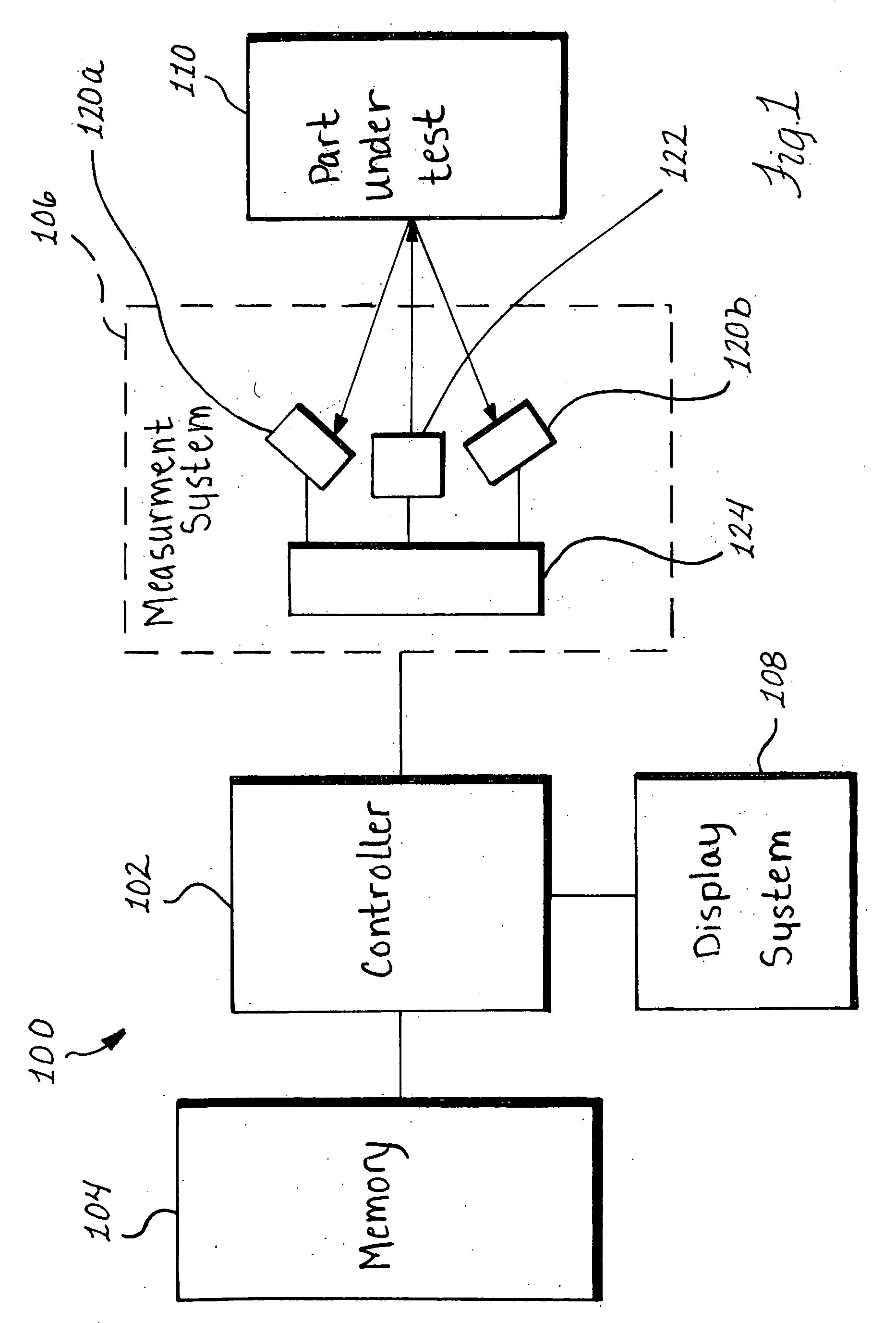
[0045] Referring initially to FIG. 1, a system 100 for graphically displaying energy measurement information for a part under test 110 preferably includes a controller 102, a memory 104, a measurement system 106 and a display system 108. The controller 102 is communicatively coupled to the memory 104, the measurement system 106, and the display system 108. The measurement system 106 preferably includes an energy emitter 122, energy detectors 120a and 120b, and a control module 124. As will be explained in greater detail below, the emitter 122, under the control of the control module 124, directs energy to the part under test 110, and the detectors 120a and 120b detect resultant energy from the part under test 110. The directed energy may include any form of energy, for instance, x-rays or thermal energy. The resultant energy detected by the detectors 120a and 120b may be diffracted energy or attenuated energy. Other forms of directed and resultant energy are possible. In accordance ...


PUM


Abstract

A system and method for displaying graphical information indicative of a plurality of material characteristics for a portion of a part under test. Energy is directed at the selected portion of the part under test. Resultant energy is detected from the selected portion of the part under test and data representative of each of a plurality of material characteristics for the portion of the part under test is obtained based, at least in part, upon the detected energy. A plurality of graphs is formed based upon the obtained data. Each of the graphs has information indicative of a separate one of the plurality of material characteristics. The plurality of graphs is displayed discrete from each other in a manner that facilitates substantially simultaneous visual comparisons between the information contained in each of the plurality of graphs.

Description

FIELD OF THE INVENTION [0001] The invention relates to systems and methods for displaying a plurality of material characteristics in a format that facilitates comparisons between the characteristics. BACKGROUND OF THE INVENTION [0002] The failure of fatigue-limited components in various types of systems often leads to undesirable or tragic consequences. For instance, the failure of a critical component of a jet engine during the operation of the engine may result in the loss of human life or other tragic results. Directed energy measurement techniques have been developed to test these critical components, detect defective components, and prevent undesirable situations from ever taking place. [0003] Typically, directed energy measurement techniques involve directing energy at a part under test and sensing the resulting diffracted energy and / or attenuated energy. If a diffraction technique is used, the resulting sensed diffraction peak is interpreted to arrive at a measurement of a ma...

Claims


Application Information

Patent Timeline
Patent Type & Authority Applications(United States)
IPC IPC(8): G06T11/20
CPCG06T11/206G01N2223/053
Inventor BRAUSS, MICHAEL
Owner PROTO MANUFACTURING LTD
Why Eureka
Try Eureka