Optical disk

a technology of optical disks and optical disks, applied in the field of optical disks, can solve the problems of reducing the size of the region to which the visible image is to be formed, not only requiring labor, and affecting the replay of signals recorded on the disk

Inactive Publication Date: 2005-05-12
SANYO ELECTRIC CO LTD
View PDF9 Cites 22 Cited by
  • Summary
  • Abstract
  • Description
  • Claims
  • Application Information

AI Technical Summary

Problems solved by technology

Attaching a label or the like or writing the name of the song or the like not only requires labor, but may also adversely affect replay of signals recorded on the disk.
Because, in a related art, a visible image is formed on a signal surface onto which the data signals are recorded, when the amount of recorded data signals is increased, the size of a region to which the visible image is to be formed is reduced, and there is a problem in that not all of the recorded data signals can be shown with the visible image.
In addition, because the formation operation of the visible image on the optical disk is performed with respect to a surface opposite to the signal recording surface of the disk, the user must perform an operation to flip the disk over after the recording operation to the disk is completed, resulting in a problem that the operability is low.

Method used


Image

  • Optical disk
  • Optical disk
  • Optical disk

Examples


Embodiment Construction

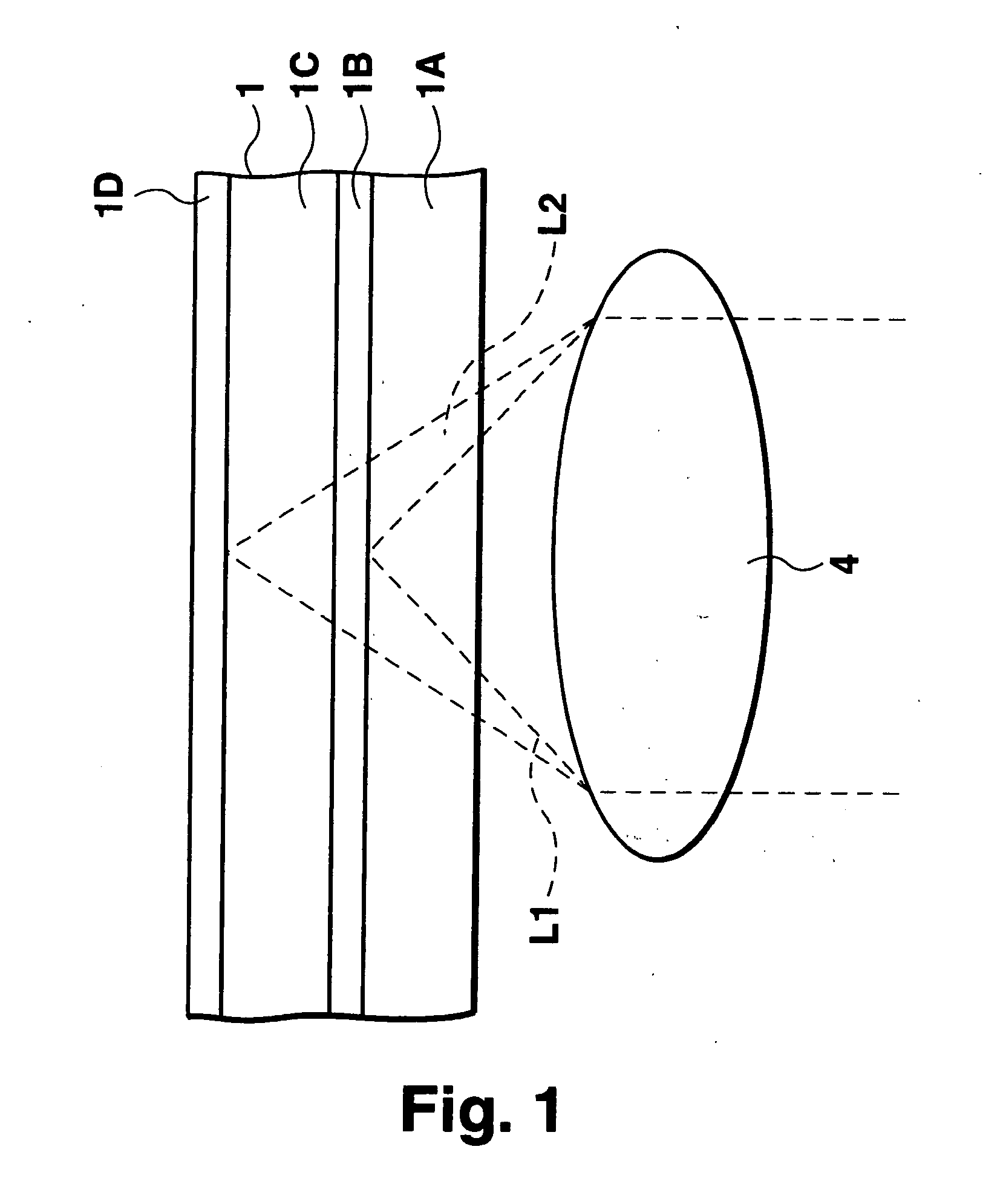
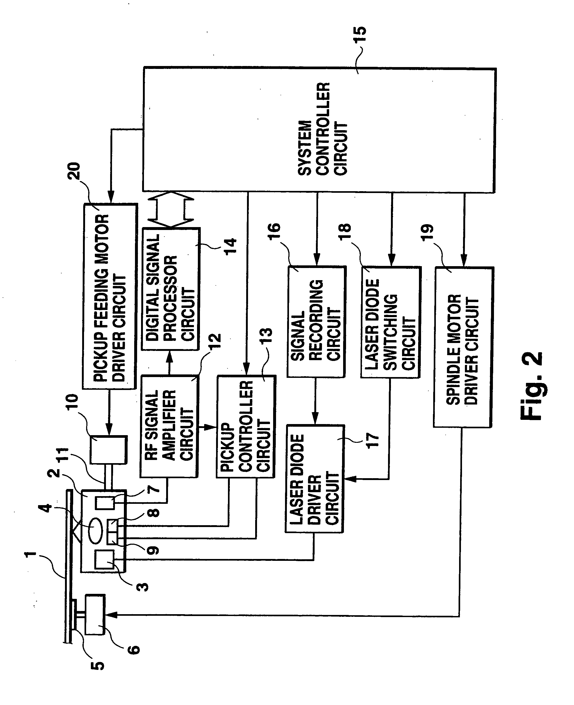
[0014]FIG. 1 is a cross sectional view of an optical disk according to a first preferred embodiment of the present invention. FIG. 2 is a block circuit diagram showing an optical disk recording and replaying apparatus which uses an optical disk according to the first preferred embodiment of the present invention. FIG. 3 is a cross sectional view showing an optical disk according to a second preferred embodiment of the present invention.

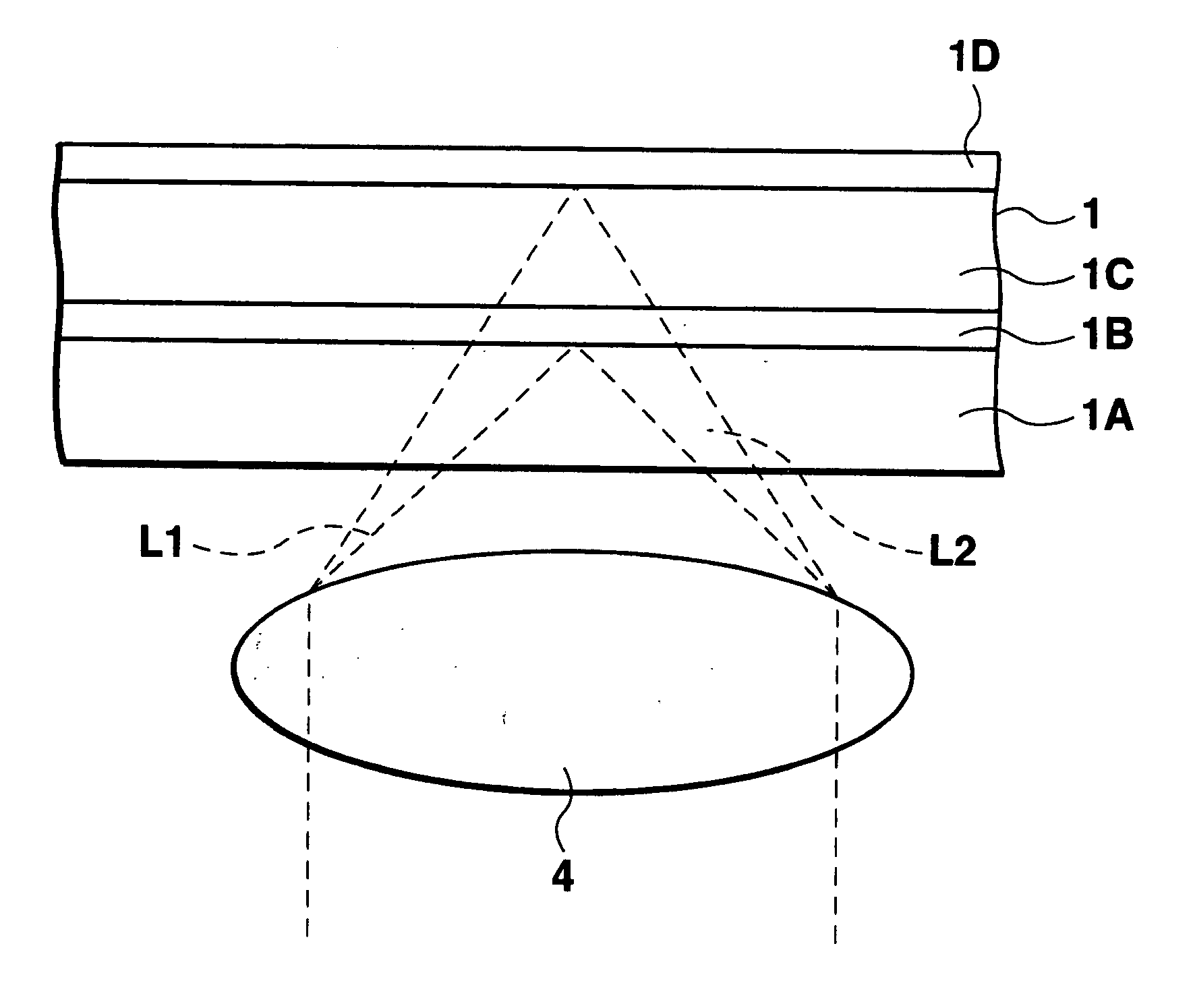
[0015] As shown in FIG. 1, an optical disk 1 according to the first preferred embodiment of the present invention comprises a first protective layer 1A which is transparent, a first signal layer 1B, a second protective layer 1C which is transparent, and a second signal layer 1D, formed from the side of a light incident surface to which a laser ray irradiated from a laser diode 3 equipped in an optical pickup device 2 is incident. The laser diode 3 equipped in the optical pickup device 2 is a dual-wavelength laser which irradiates two laser rays L1 an...


PUM

PropertyMeasurementUnit
colorsaaaaaaaaaa
opticalaaaaaaaaaa
photosensitiveaaaaaaaaaa

Abstract

An optical disk to which a laser ray irradiated from an optical pickup device equipped in an optical disk recording and replaying apparatus is incident, comprises two signal layers including a first signal layer and a second signal layer formed from a light incident surface side, wherein a visible image can be formed in the second signal layer (1D) by a laser ray irradiated from the light incident surface side.

Description

CROSS-REFERENCE TO RELATED APPLICATIONS [0001] The priority Japanese Patent Application Number 2003-380612 upon which this patent application is based is hereby incorporated by reference. BACKGROUND OF THE INVENTION [0002] 1. Field of the Invention [0003] The present invention relates to an optical disk in which a visible image can be formed on the disk using a laser ray irradiated from an optical pickup device. [0004] 2. Description of the Related Art [0005] Disk players in which signals recorded on a disk are read using an optical pickup device are widely in use. Recently, optical disk recording and replaying apparatuses having a functionality to record signals onto a disk using a laser ray irradiated from an optical pickup device in addition to the replaying function have been commercialized. [0006] When a signal is recorded on a disk using an optical disk recording and replaying apparatus, in order to see the contents of the signals recorded on the disk, it is necessary to repla...

Claims


Application Information

Patent Timeline
Patent Type & Authority Applications(United States)
IPC IPC(8): G11B7/0037G11B7/0045G11B7/24035G11B7/24038G11B7/24094G11B7/24097G11B23/40
CPCG11B7/0037G11B23/40G11B7/24038
Inventor YAMAMOTO, TSUYOSHIHATTORI, KATSUKIKOBAYASHI, SHINJIWATANABE, HIROSHIFUMA, MASATOTSUKIHASHI, AKIRA
Owner SANYO ELECTRIC CO LTD
Why Eureka
Try Eureka