Ethernet OAM performance management

a performance management and ethernet technology, applied in the field of communication networks, can solve the problems of inability to enable certain operations, ethernet was felt to be inappropriate for deployment in these types, and ethernet did not enable certain operations, administration and maintenance (oam) operations to take pla

Inactive Publication Date: 2005-05-12
RPX CLEARINGHOUSE +1
View PDF11 Cites 139 Cited by
  • Summary
  • Abstract
  • Description
  • Claims
  • Application Information

AI Technical Summary

Benefits of technology

[0009] Performance management may be provided in an Ethernet network by defining maintenance entities and measuring performance of the maintenance entities on the network. Maintenance entities may be defined between any two flow points on the network, for example between customer flow points, provider flow points, or both, and may include, for example, access link, intra-domain, and inter-domain maintenance entities. The maintenance entities may be defined on a link basis or service basis, and may be used to measure performance of various aspects of the Ethernet network. Maintenance entities may be used to monitor performance within a given provider's network, as well as across the provider's network so that performance can be measured end-to-end across a network. The invention is not limited to the use of these particular maintenance entities.
[0010] The maintenance entities may be used to monitor various performance parameters, such as frame loss, frame delay

Problems solved by technology

Specifically, network providers such as carriers were reluctant to deploy networks based on Ethernet technology, since Ethernet is designed to provide best efforts service and doesn't support Operation, Administration, and Maintenance (OAM) functions desired by the network providers.
Since network providers need to be able to guarantee connectivity, Ethernet was felt to be inappropriate for deployment in these types of networks.
Unfortunately, although it may be possible to overcome the limitations associated with the best-efforts nature of the Ethernet technology, other aspects of the Ethernet protocol still remain to

Method used


Image

  • Ethernet OAM performance management
  • Ethernet OAM performance management
  • Ethernet OAM performance management

Examples


Embodiment Construction

[0022] The following detailed description sets forth numerous specific details to provide a thorough understanding of the invention. However, those skilled in the art will appreciate that the invention may be practiced without these specific details. In other instances, well-known methods, procedures, components, protocols, algorithms, and circuits have not been described in detail so as not to obscure the invention.

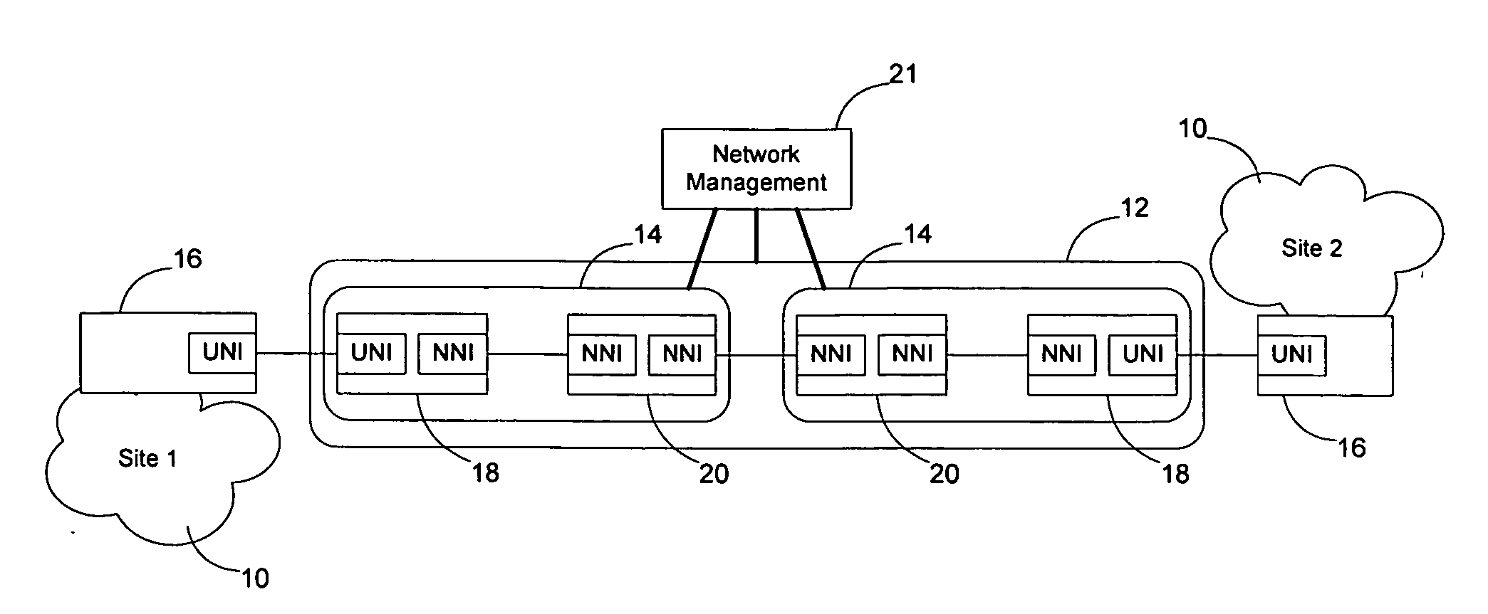
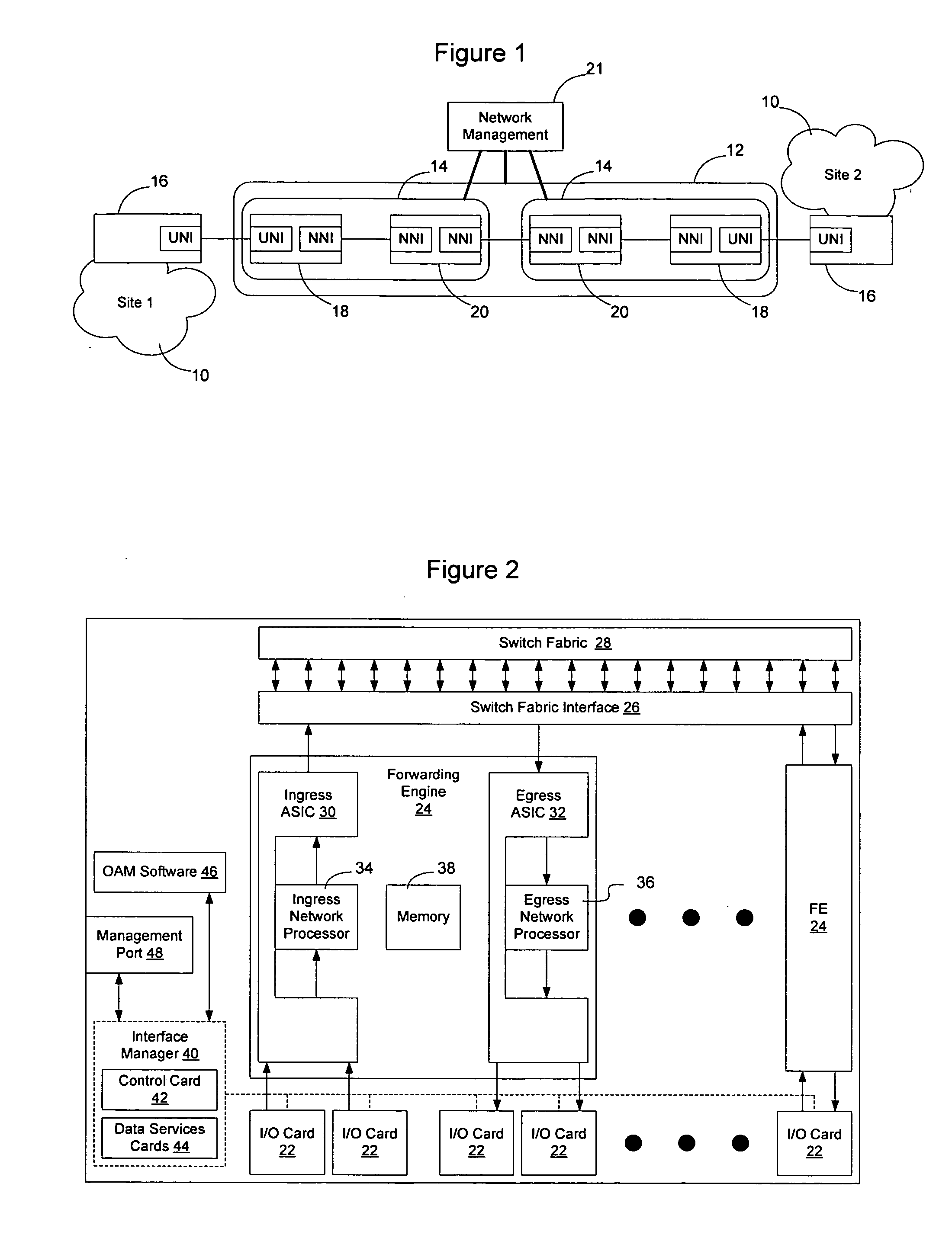
[0023]FIG. 1 illustrates an example of a network topology in which customer sites 10 running a conventional protocol such as Ethernet are interconnected over a network 12. Multiple carriers 14 may participate in handling data flowing between the sites over the network, and each of the carrier networks may have multiple domains. Each customer site 10 is connected to the provider's 12 using a Customer Edge (CE) network element 16. Network elements within the provider's network that interface CE network elements will be referred to herein as Provider Edge (PE) network elem...


PUM


Abstract

Maintenance entities may be defined between customer and provider flow points to allow performance management to take place on an Ethernet network. The maintenance entities may be defined for access link, intra-domain, and inter-domain, and may be defined on a link or service basis. The maintenance entities may be used to monitor performance within a network or across networks, and may be used to monitor various performance parameters, such as frame loss, frame delay, frame delay variation, availability, errored frame seconds, service status, frame throughput, the number of frames transmitted, received or dropped, the status of a loopback interface, the amount of time a service has been unavailable, and many other parameters. Several management mechanisms may be used, and the measurements may be collected using a solicited collection method, in which a responses are required and collected, or an unsolicited collection method in which a response is not required.

Description

CROSS REFERENCE TO RELATED APPLICATIONS [0001] This application claims the benefit of and priority from the following five Provisional U.S. Patent Applications: 60 / 518,910, filed Nov. 10, 2003, entitled “Proposal for OAM Domain,” 60 / 518,920, filed Nov. 10, 2003, entitled “Proposal For Connectivity Check Function For Fault Management In Ethernet OAM,” 60 / 518,919, filed Nov. 10, 2003, entitled “Proposal For Non-Intrusive Loopback For Fault Management In Ethernet OAM,” 60 / 518,912, filed Nov. 10, 2003, entitled “Proposal For Path Trace Function For Fault Management In Ethernet Networks,” and 60 / 535,018, filed Jan. 7, 2004, entitled “Ethernet OAM: Performance Management.” The content of each of these five applications is hereby incorporated herein by reference.BACKGROUND OF THE INVENTION [0002] 1. Field of the Invention [0003] The present invention relates to communication networks and, more particularly, to Ethernet Operation Administration and Maintenance (OAM) domains and an Ethernet ...

Claims


Application Information

Patent Timeline
IPC IPC(8): H04L12/26
CPCH04L41/04H04L43/0852H04L43/08H04L41/34
Inventor MOHAN, DINESHHOLNESS, MARC
Owner RPX CLEARINGHOUSE
Why Eureka
Try Eureka