

Image forming apparatus
- Summary
- Abstract
- Description
- Claims
- Application Information
AI Technical Summary
Benefits of technology
Problems solved by technology
Method used
Image

Examples
embodiment 1
1) Example of Image Forming Apparatus
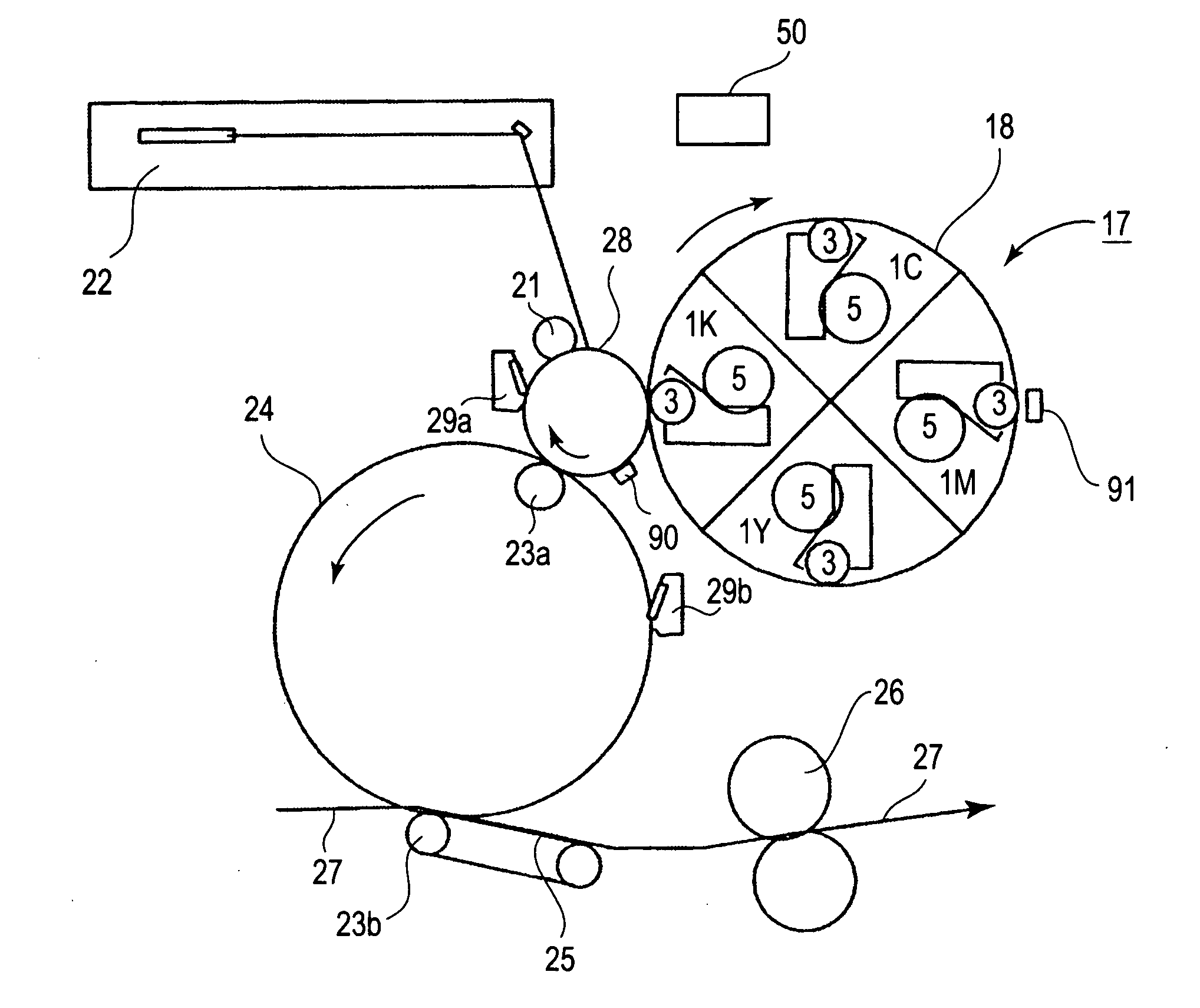
[0028]FIG. 1 is a schematic sectional view of an image forming apparatus in this embodiment, showing the general structure thereof. First, the overall structure of the image forming apparatus will be described. The image forming apparatus in this embodiment is a color laser printer which uses an electrophotographic process, a rotary developing method, and an intermediary transfer system employing a transfer drum.
[0029] This image forming apparatus comprises: an electrophotographic photosensitive member (which hereinafter will be referred to as photosensitive drum) 28 as an image bearing member which is in the form of a rotatable drum and is rotationally driven at a predetermined peripheral velocity in the clockwise direction, or the direction indicated by an arrow mark; a primary charging device 21 for uniformly charging the peripheral surface of the photosensitive drum 28 to predetermined polarity and potential level; a laser based exposing a...
embodiment 2
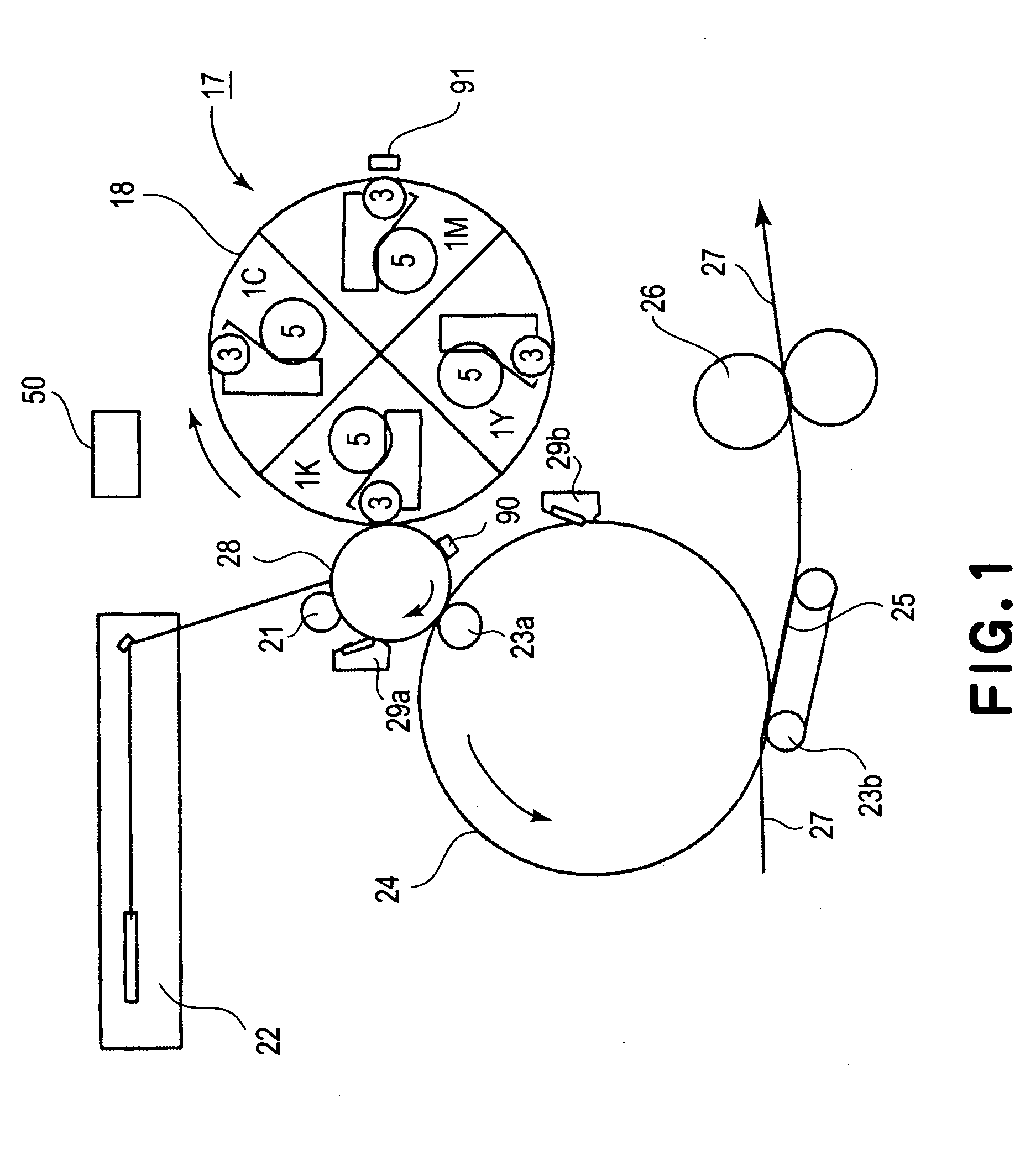
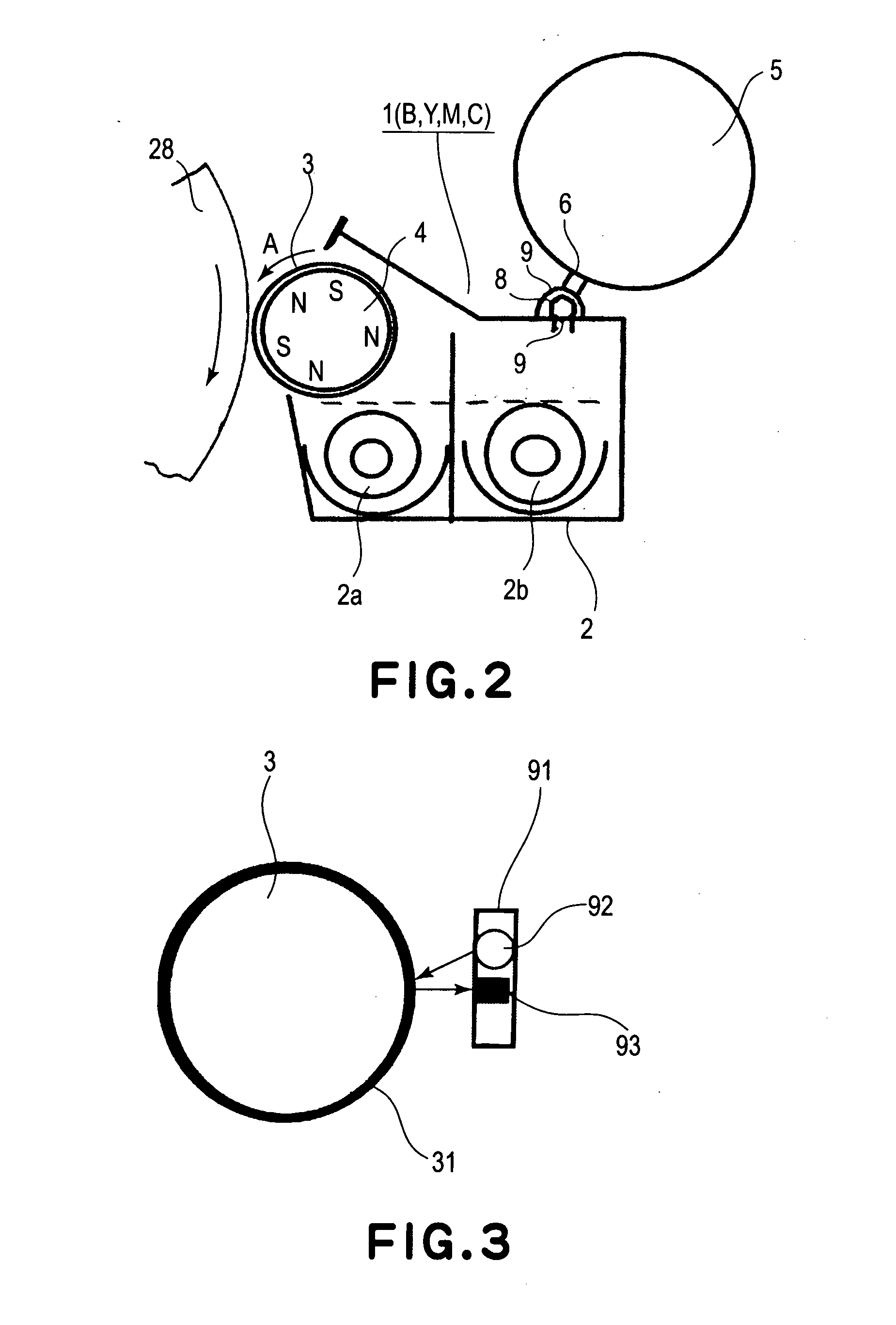
[0063] The structure of the image forming apparatus in this embodiment is the same as that of the image forming apparatus in the first embodiment, except for the following feature which characterizes this embodiment. That is, in this embodiment, when detecting the amount of the light reflected by the developer layer on the peripheral surface of the development sleeve with the use of a density sensor, the first and second stirring screws 2a and 2b as developer supplying means for supplying the development sleeve 3 with the developer stored in the developing device 2, are rotated along with the development sleeve 3, for a predetermined length of time, under the condition in which toner cannot be adhered to the photosensitive drum 28. In other words, in this embodiment, before detecting the amount of the light reflected by the developer layer on the peripheral surface of the development sleeve 3, the photosensitive drum 28 is rotated no less than one full turn while being cleared of el...
embodiment 3
[0066] The structure of the image forming apparatus in this embodiment is shown in FIG. 10. The image forming apparatus in this embodiment is characterized in that the toner cartridge 5 of the black color developing device 1K among the plurality of the developing devices thereof is larger than the toner cartridges 5 for the other developing devices.
[0067] Generally, the number of the monochromatic images formed by an ordinary user of an image forming apparatus, or the number of the monochromatic originals copied by the ordinary user, is substantially greater than the number of full-color images formed by the ordinary user, or the full-color originals copied by the ordinary user. Therefore, the amount by which the black toner is consumed is likely to be greater than the amounts by which the toners of the other colors are consumed. Thus, if all the toner cartridges 5 are made equal in size, the frequency with which the black toner cartridge must be replaced is higher than the frequen...
PUM
 Abstract
Description
Claims
Application Information