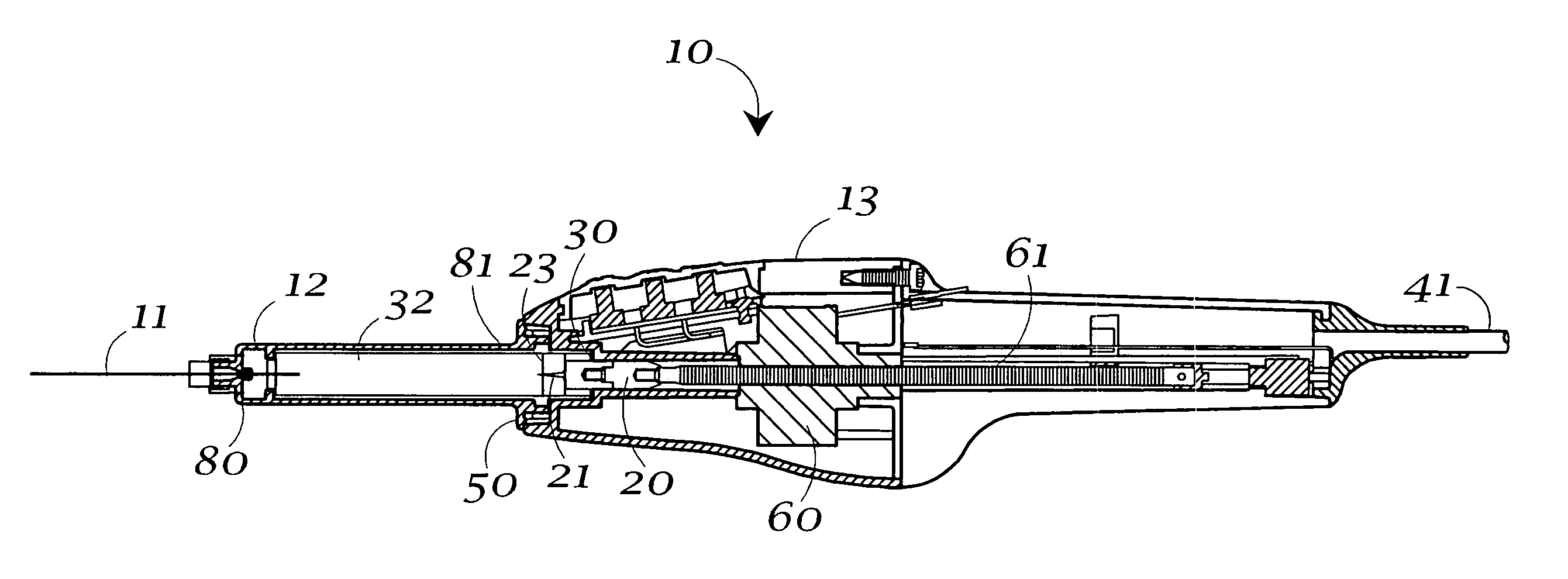
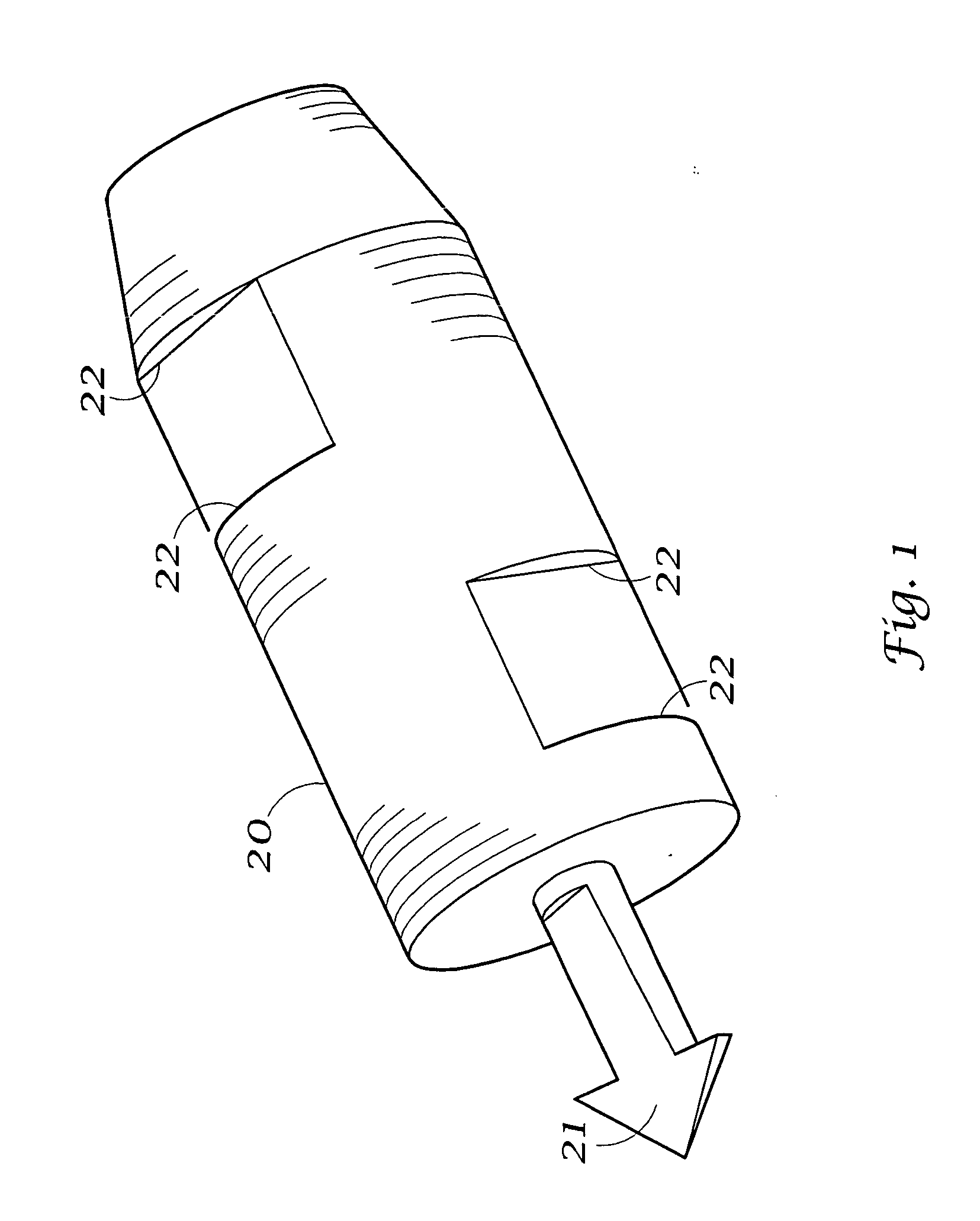
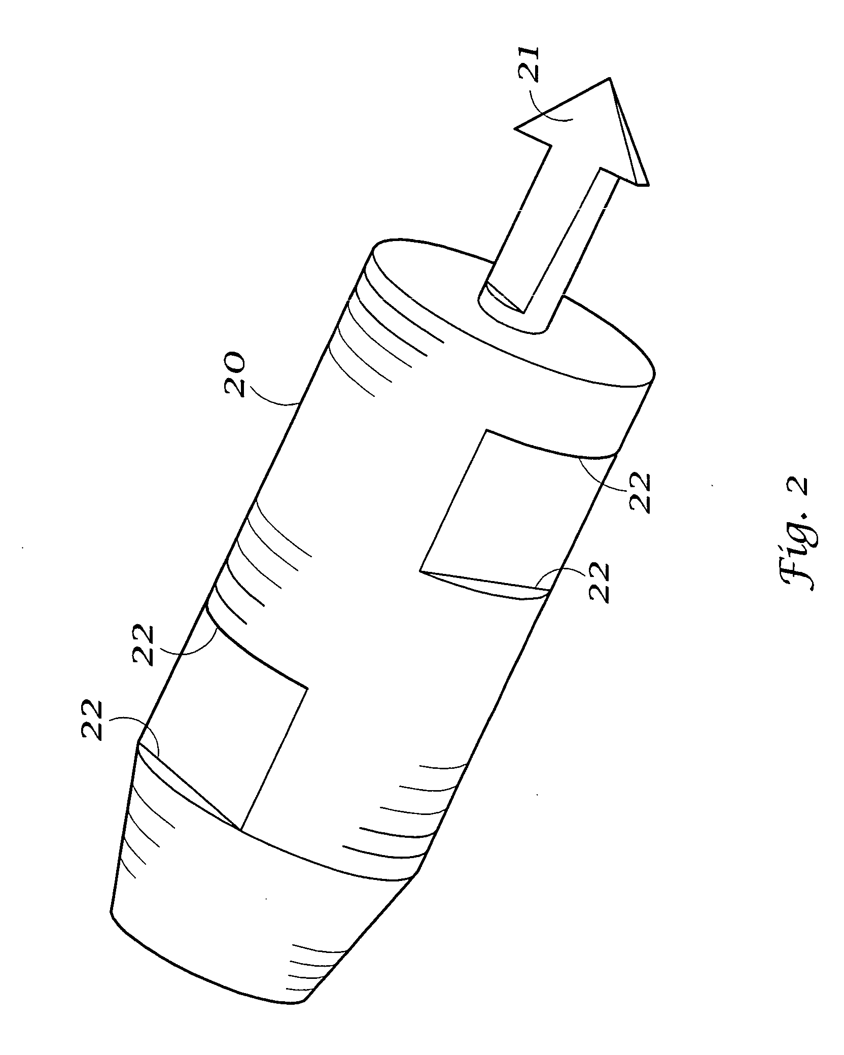
[0015] In general, an electrically controlled syringe for dispensing a fluid material, comprises a power drive unit electrically and operatively connected to a syringe unit via at least one connecting conduit; said syringe unit having a releasably connected carpule holder, said carpule holder being initially loaded with the material to be dispensed, said carpule holder being releasably connected at one end to said syringe unit and fluidly connected at its other end to a dispensing needle, said carpule holder having a rubber-like plunger seal laterally displaceable therein between a dispensing and a retracted position, such that when said carpule plunger seal is moved toward a dispensing position, the material in said carpule holder is caused to flow through said dispensing needle; a longitudinally movable, powered drive shaft in said syringe unit and releasably connected to said carpule plunger seal, said drive shaft having an end proximal to and an end distal to said carpule plunger seal when said carpule holder is in place on said syringe unit; wherein said drive shaft is provided with a harpoon at said proximal end; said harpoon having a swept-back, barbed point and knife edges along its length, such that said barbed point is insertable into said rubber-like carpule plunger seal, and is selectively prevented from being removed by physical contact between said barbed point and said carpule plunger seal; an electric drive motor operatively affixed to said drive shaft, and operatively connected to said power drive unit, such that the rate of and direction of the longitudinal displacement of said drive shaft is selectable by electrical, operative signals received from said power drive unit to cause said drive motor to displace said drive shaft in a selected longitudinal direction at a selected rate, thereby laterally displacing said operatively connected harpoon and carpule plunger seal, said drive motor being operable with electric power received from said power drive unit; said harpoon being fabricated from a hard, corrosion resistant, sterilizable material; a stripper ring positioned within said syringe unit and proximate to said carpule plunger seal when said carpule holder is in place upon said syringe unit, such that when said carpule plunger seal is moved from the dispensing to the retracted position, said stripper ring physically engages said carpule plunger seal, preventing further retracting movement of said carpule plunger seal and hence, allowing extraction of said harpoon from said carpule plunger seal; said stripper ring having an inside diameter larger than said harpoon such that said harpoon is receivable therein; and at least one secondary injection control mechanism located proximate to said syringe unit and distal to said power drive unit, wherein said secondary injection control mechanism is operatively connected to said syringe drive motor to control the longitudinal displacement direction or rate of said drive shaft, and hence, the injection rate of the material dispensed from said needle.
[0016] In another embodiment of the invention, an electrically controlled syringe for dispensing a fluid material comprises a power drive unit electrically and operatively connected to a syringe unit via at least one connecting conduit; said syringe unit having a releasably connected carpule holder, said carpule holder being initially loaded with the material to be dispensed, said carpule holder being releasably connected at one end to said syringe unit and fluidly connected at its other end to a dispensing needle, said carpule holder having a rubber-like plunger seal laterally displaceable therein between a dispensing and a retracted position, such that when said carpule plunger seal is moved toward a dispensing position, the material in said carpule holder is caused to flow through said dispensing needle; a longitudinally movable, powered drive shaft in said syringe unit and releasably connected to said carpule plunger seal, said drive shaft having an end proximal to and an end distal to said carpule plunger seal when said carpule holder is in place on said syringe unit; wherein said drive shaft is provided with a harpoon at said proximal end; said harpoon having a swept-back, barbed point and knife edges along its length, such that said barbed point is insertable into said rubber-like carpule plunger seal, and is selectively prevented from being removed by physical contact between said barbed point and said carpule plunger seal; an electric drive motor operatively affixed to said drive shaft, and operatively connected to said power drive unit, such that the rate of and direction of the longitudinal displacement of said drive shaft is selectable by electrical, operative signals received from said power drive unit to cause said drive motor to displace said drive shaft in a selected longitudinal direction at a selected rate, thereby laterally displacing said operatively connected harpoon and carpule plunger seal, said drive motor being operable with electric power received from said power drive unit; said harpoon being fabricated from a hard, corrosion resistant, sterilizable material; and at least one secondary injection control mechanism located proximate to said syringe unit and distal to said power drive unit, wherein said secondary injection control mechanism is operatively connected to said syringe drive motor to control the longitudinal displacement direction or rate of said drive shaft, and hence, the injection rate of the material dispensed from said needle.
[0017] A computer controlled syringe for dispensing a fluid material also comprises a power drive unit electrically and operatively connected to a syringe unit via at least one connecting conduit; said power drive unit including a logic control circuit; said syringe unit having a releasably connected carpule holder, said carpule holder being initially loaded with the material to be dispensed, said carpule holder being releasably connected at one end to said syringe unit and fluidly connected at its other end to a dispensing needle, said carpule holder having a rubber-like plunger seal laterally displaceable therein between a dispensing and a retracted position, such that when said carpule plunger seal is moved toward a dispensing position, the material in said carpule holder is caused to flow through said dispensing needle; a longitudinally movable, powered drive shaft in said syringe unit and releasably connected to said carpu


