Subcutaneous, intramuscular bearing for a rigid transcutaneous implant

a transcutaneous implant and intramuscular bearing technology, applied in bone implants, artificial legs, medical science, etc., can solve the problems of contamination, flexible material, silicone, piercing, etc., and achieve the effect of preventing inadvertent removal of the germ barrier and preventing contamination of the poin

Inactive Publication Date: 2005-05-12
ORTHODYNAMICS GMBH
View PDF4 Cites 42 Cited by
  • Summary
  • Abstract
  • Description
  • Claims
  • Application Information

AI Technical Summary

Benefits of technology

[0005] Against this background, it is now an object of the present invention to improve a conventional subcutaneous, intramuscular bearing of the type mentioned at the outset, such that safety against contamination of the point in the body where the implant emerges (emergence point) and the adjacent regions of the thigh stump is significantly increased, and inadvertent removal of the germ barrier is prevented.

Problems solved by technology

Even if this known bearing is successfully inserted in practice, there is the risk that in the case, for example, when the point where the implant emerges through the thigh stump is cleaned with a hollow needle, the flexible material, in most cases silicone, is also pierced and a contamination occurs.

Method used


Image

  • Subcutaneous, intramuscular bearing for a rigid transcutaneous implant
  • Subcutaneous, intramuscular bearing for a rigid transcutaneous implant
  • Subcutaneous, intramuscular bearing for a rigid transcutaneous implant

Examples


Embodiment Construction

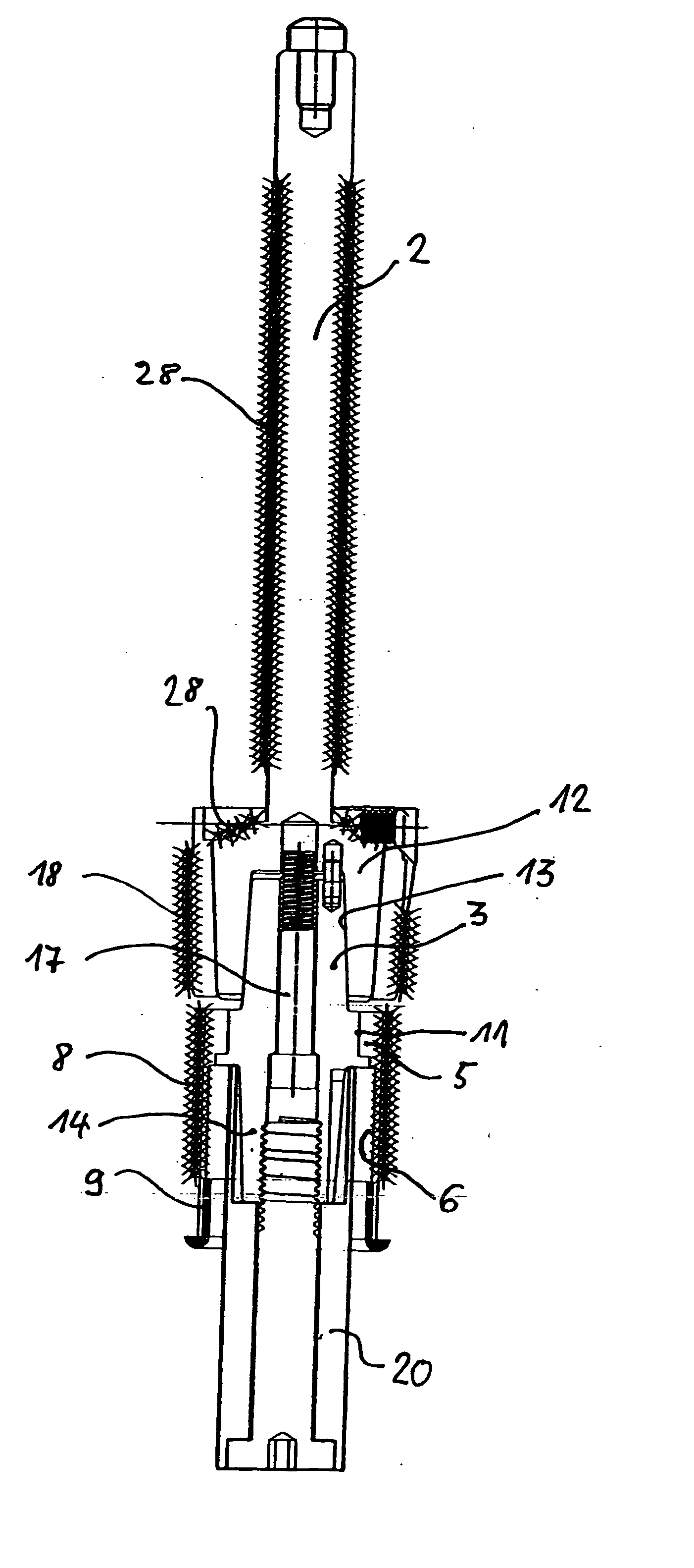
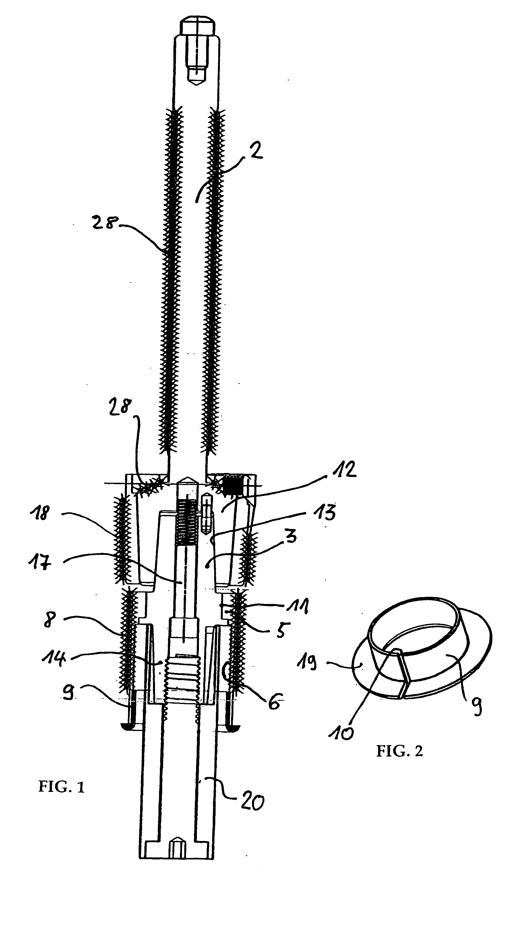
[0032]FIG. 1 gives a first overview. A rigid transcutaneous implant 2 is inserted into a femur stump (not shown). The open meshed, three-dimensional lattice structure 28 is used in the present case for integrating bone material for secondary fixation of the implant 2 into the bone. It is sealed on the distal end by a metal sleeve 12, which seals the femur stump. For this purpose, the metal sleeve 12 also carries a three-dimensional, open-meshed lattice structure 28, in which bone material should grow.

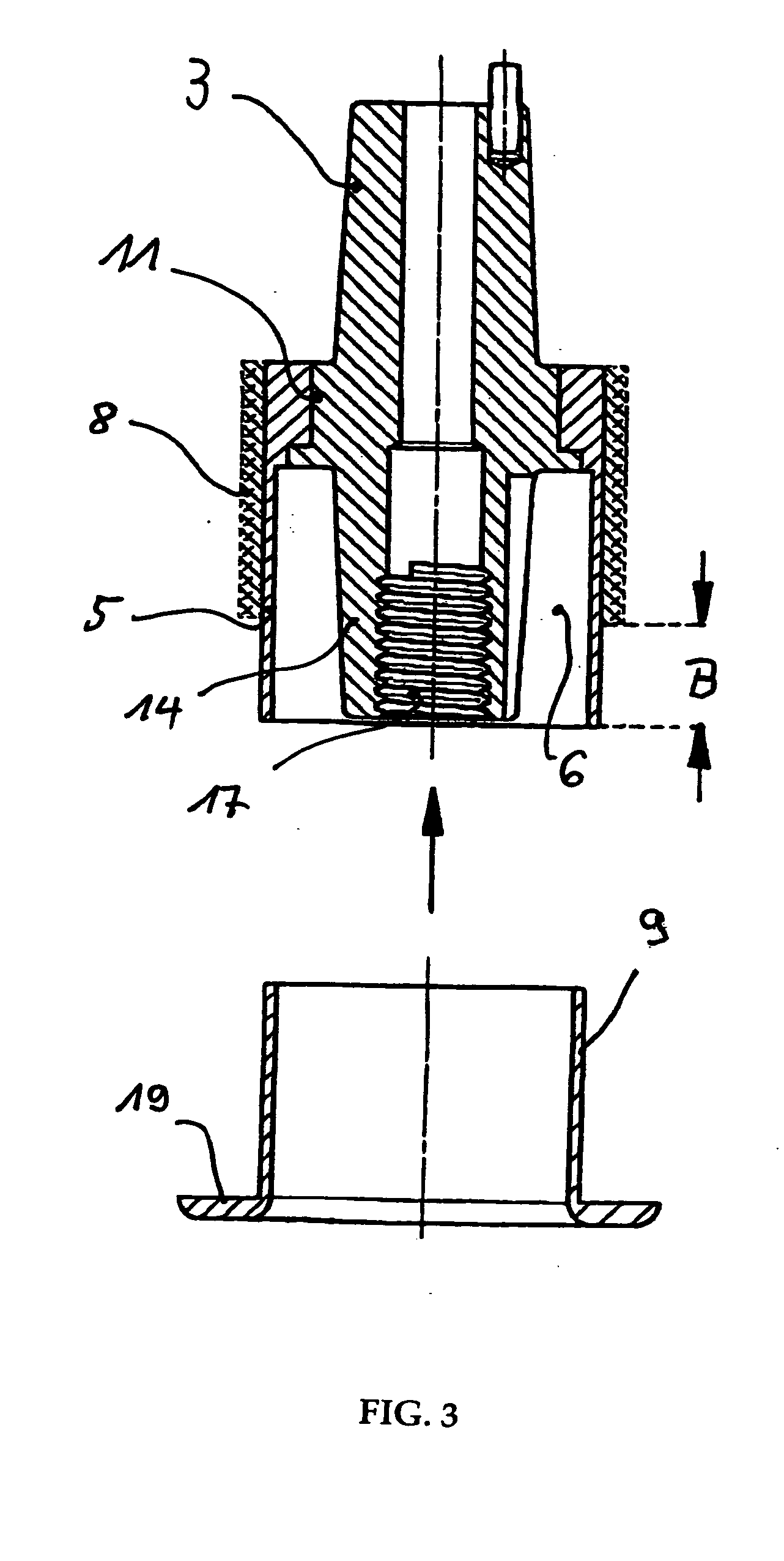
[0033] In the interior of the metal sleeve 12, a conical clamping sleeve 13 is formed. This is provided for manufacturing a conical clamp connecting with the intermediate piece 3 presently embodied as a double cone. The intermediate piece 3 has a cylindrical center section 11, on which the bushing 5 is heat-shrunk. Another cone 14 connects to the center section 11 on the distal side for producing a conical clamp with a conical clamping sleeve in an adapter of the extracorporal coupling...


PUM


Abstract

A subcutaneous, intramuscular bearing (1) for a rigid transcutaneous implant (2) is provided, for anchoring intracorporally in a bone stump and having an intermediate piece (3) between the implant (2) and an extracorporal coupling for coupling on the implant. A rigid bushing (5) is tightly connected to the intermediate piece (3), such that between the wall of the bushing (5) and the intermediate piece (3) an annular space (6) is formed, which is closed in the intracorporal direction, for receiving and setting the extracorporal coupling. The outer wall of the bushing (5) has an open-meshed, three-dimensional lattice structure (8) and a lattice-free distal region having a width B. A spring ring (9) is set in the annular space (6) from the distal end, moved with a telescoping motion, and locked under exertion of its spring effect.

Description

BACKGROUND OF THE INVENTION [0001] The invention relates to a subcutaneous, intramuscular bearing for a rigid transcutaneous implant, which can be anchored intracorporally in a bone stump and which has an intermediate piece between the implant and an extracorporal coupling that can be coupled to this intermediate piece. [0002] Such a bearing is known from German published patent application DE 100 40 590 A1. The bearing described in this publication comprises a flexible material and it has a bushing, which closely surrounds the implant distally. The bearing also has an intracorporally arranged coupling sleeve in the form of flexible pleated bellows, which is proximally connected to the bushing in a sealed manner with a molded collar, such that a hollow space of a minimum width remains free between the inner wall of the pleated bellows and the outer wall of the bushing. In this way, a flexible lattice network is arranged distally on the pleated bellows and is connected on the distal ...

Claims


Application Information

Patent Timeline
Patent Type & Authority Applications(United States)
IPC IPC(8): A61F2/00A61F2/28A61F2/30A61F2/46A61F2/50A61F2/78
CPCA61F2/2814A61F2250/0068A61F2/30742A61F2/30749A61F2/30942A61F2/4637A61F2/4657A61F2/78A61F2002/30013A61F2002/30204A61F2002/30235A61F2002/30341A61F2002/30344A61F2002/30354A61F2002/30382A61F2002/30434A61F2002/30497A61F2002/30507A61F2002/3055A61F2002/30574A61F2002/30594A61F2002/30677A61F2002/3068A61F2002/30738A61F2002/30822A61F2002/30909A61F2002/3093A61F2002/4658A61F2002/7887A61F2220/0025A61F2220/0033A61F2220/0041A61F2230/0065A61F2230/0069A61F2250/0024A61F2250/0067A61F2/30723A61F2002/30011A61F2002/302A61F2002/30331A61F2002/30339A61F2002/30433A61F2002/30495
Inventor GRUNDEI, HANS
Owner ORTHODYNAMICS GMBH
Why Eureka
Try Eureka