Tubular monitor systems and methods

a technology of monitoring system and tube, applied in the field of tube monitoring system and method, can solve the problem of often unknown loading amoun

Inactive Publication Date: 2005-05-19
COILED TUBING ENG SERVICES
View PDF21 Cites 71 Cited by
  • Summary
  • Abstract
  • Description
  • Claims
  • Application Information

AI Technical Summary

Benefits of technology

[0017] In certain aspects, systems according to the present invention measure the strains in a section of pipe in the structure caused by one or more of these loads and stresses. Hoop strain is strain around a structure's circumference. Taken at a single point, hoop strain is the same as tangential strain. Axial strain is strain along a structure's longitudinal axis. Such systems can also measure some of the loads directly. For example, in one aspect the system measures temperature and internal pressure directly while measuring strains in the pipe to determine the other loads. Such a system may, according to the present invention, also use a weight measurement provided from another existing measurement system. To measure pressures, in one aspect a commercially available diaphragm pressure gauge apparatus is used that has one or more fiber optic strain gauges. Alternatively, commercially available electric temperature and pressure gauges are used.

Problems solved by technology

However, as various oilfield operations become more complex, the amount of loading is often unknown.

Method used


Image

  • Tubular monitor systems and methods
  • Tubular monitor systems and methods
  • Tubular monitor systems and methods

Examples


Embodiment Construction

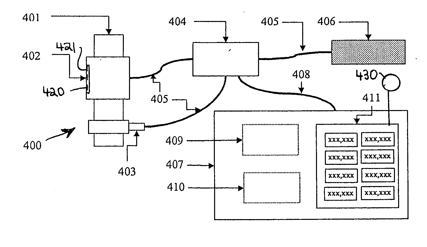
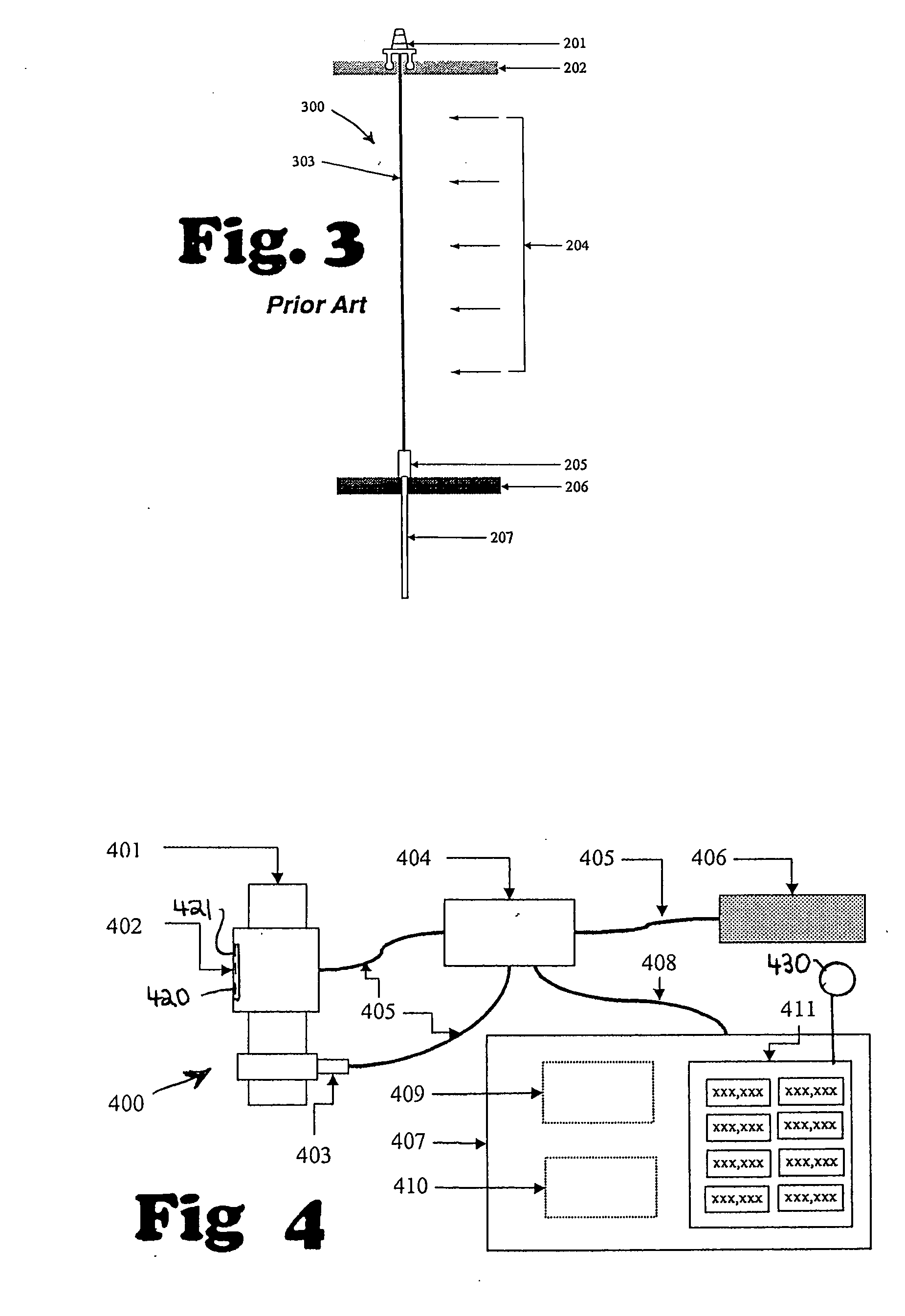
[0030] A system 400, according to the present invention as shown schematically in FIGS. 4 and 5 has a strain measuring device 402 on a section of pipe 401 which may be a section of lubricator or riser. The pipe 401 is instrumented with one or more strain gauges 420 and one or more temperature gauges 421. These gauges include signal production and signal transmission apparatus for sending signals to processing equipment, e.g. computer(s). This component of the system is referred to as the “strain measuring device” or “SMD”. There may be multiple SMDs in a system according to the present invention. It is to be understood that according to the present invention instead of a pipe 401 the system 400 (and other embodiments herein) can be used to measure parameters of a structure, e.g., but not limited to, a lubricator, a lubricator stack, a riser (surface or subsea), a tubular string, or a pipe support.

[0031] Temperature, one of the parameters measured by this device, is used to adjust t...


PUM

PropertyMeasurementUnit
heightaaaaaaaaaa
bending momentaaaaaaaaaa
temperatureaaaaaaaaaa

Abstract

A system for measuring parameters of a structure, the system in certain aspects having a plurality of strain gauges emplaceable on the structure, signal transmission apparatus associated with the plurality of strain gauges for transmitting signals therefrom indicative of gauge measurements to computer apparatus for processing the signals, the gauges, in one aspect, including at least three strain gauge apparatuses for providing axial strain measurements, and computer apparatus for receiving signals from the transmitting apparatus indicative of the measurements and for determining bending moment and bending direction of the structure at a location of the gauge apparatuses, and in one aspect wherein the computer apparatus is programmed to calculate internal pressure and/or bending direction of the structure based on the measurements, and in one aspect to do so in real time.

Description

BACKGROUND OF THE INVENTION [0001] 1. Field of the Invention [0002] The present invention is directed to tubular monitoring systems and methods. [0003] 2. Description of Related Art [0004] There are many situations where tubulars, e.g. pipe or risers, are used both for their mechanical stiffness and their pressure containing abilities. In many of these applications, such as pipelines, pipe is basically static during its life, with fairly constant loading conditions. In other applications, such as risers and lubricators, there is dynamic movement of the pipe structure and / or variable loading conditions. [0005]FIG. 1 illustrates a prior art well intervention system 100 using coiled tubing (“CT”), which includes a lubricator 104. The height of this system may typically be 20 to 100 ft. The CT 108 passes around a guide arch 101 and into an injector 102, down through a stripper 103, the lubricator 104, a blow out preventer (“BOP”) 105, a wellhead 106 [these items in combination sometimes...

Claims


Application Information

Patent Timeline
Patent Type & Authority Applications(United States)
IPC IPC(8): E21B47/00G01L1/22G01L3/10G01L9/00
CPCE21B47/0006G01L9/0002G01L3/108G01L1/2218E21B47/007
Inventor NEWMAN, KENNETH R.
Owner COILED TUBING ENG SERVICES
Why Eureka
Try Eureka