Multisource and multimaterial freeform fabrication

a freeform, multi-material technology, applied in the direction of additive manufacturing processes, electric/magnetic/electromagnetic heating, instruments, etc., can solve the problems of inability to effectively combine different materials and different sources to create functionally graded compositions or locally controlled properties, and inability to utilize high-melting point materials such as metals or ceramics

Inactive Publication Date: 2005-05-19
UNIV TECH INT
View PDF11 Cites 177 Cited by
  • Summary
  • Abstract
  • Description
  • Claims
  • Application Information

AI Technical Summary

Problems solved by technology

This process requires preparation of a raw material into a flexible filament or rigid rod and is unable to utilize high-melting point materials such as metals or ceramics.
Obviously, high part accuracy may be obtained but only at very slow build rates.
Existing rapid prototyping systems are unable to effectively combine different materials and different sources to create functionally graded compositions or locally controlled properties.

Method used


Image

  • Multisource and multimaterial freeform fabrication
  • Multisource and multimaterial freeform fabrication
  • Multisource and multimaterial freeform fabrication

Examples


Embodiment Construction

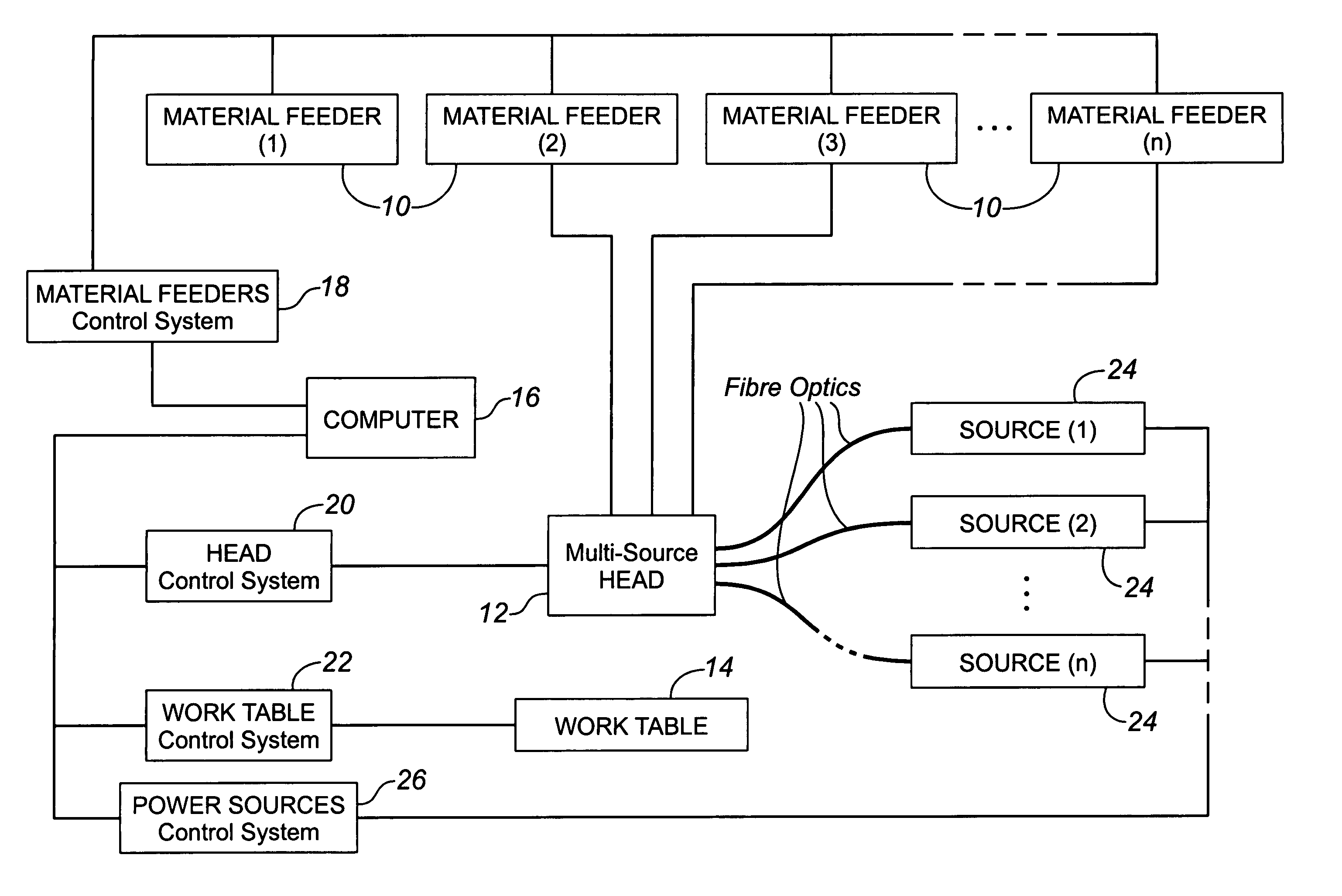
[0024] The present invention provides for an apparatus for fabricating a freeform three-dimensional object. When describing the present invention, all terms not defined herein have their common art-recognized meanings.

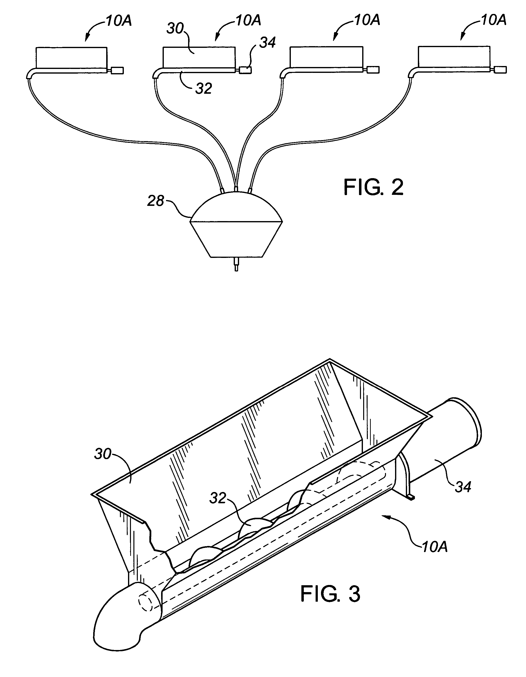
[0025] As shown schematically in FIG. 1, a system of the present invention comprises a plurality of material feeders (10) and a head unit (12). The head unit deposits the material onto a work table (14). The control of the material feeders (10), the head unit (12) and the work table (14) is accomplished by a computer (16) operating suitable control modules (18, 20, 22). Multiple energy or power sources (24) are associated with the head unit (14) and controlled by a power source control module (26), which itself is associated with the computer (16). When describing the present invention, the planar area below the head unit represented by the work table is defined by X-axis and Y-axis, which is typically but not necessarily horizontal, while the Z-axis is normal to the ...


PUM

PropertyMeasurementUnit
droplet sizesaaaaaaaaaa
poweraaaaaaaaaa
shapesaaaaaaaaaa

Abstract

An apparatus for forming freeform solid articles includes a head unit having a plurality of arc-shaped support arms. The support arms mount material feeders and power sources which are directed at a work table. The material feeders, power sources and movement of the head unit and work table are controlled by a computerized control system.

Description

CROSS REFERENCE TO RELATED APPLICATIONS [0001] This application claims the priority benefit of U.S. Provisional Application No. 60 / 481,328 filed on Sep. 4, 2003 entitled “Multisource and Multimaterial Freeform Fabrication”, the contents of which are incorporated herein by reference.BACKGROUND OF INVENTION [0002] The present invention relates to an apparatus and method for fabricating freeform solid shapes using multiple materials and multiple sources. [0003] Rapid prototyping technologies are known which incorporate solid freeform fabrication processes and machines. Such systems build an object layer by layer or point by point under the control of a computer. Typically, a computer-aided design (CAD) file which represents a desired object is sliced into a large number of thin layers, with the contours of each layer being defined to form vectors or polylines. Computer numerical control (CNC) methods are then used to drive a fabrication tool for building the object layer by layer. [000...

Claims


Application Information

Patent Timeline
Patent Type & Authority Applications(United States)
IPC IPC(8): B29C31/10B29C35/08B29C41/36B29C67/00
CPCB29C31/10B29C41/36B29C67/0081B29K2105/08B29C2035/0827B29C2035/0838B29C2035/0822B29C64/165B33Y40/00B33Y10/00B33Y30/00
Inventor GU, PEIHUAGIULIANI, VALERIO
Owner UNIV TECH INT
Why Eureka
Try Eureka