Steering device

Inactive Publication Date: 2005-05-19
NSK LTD
View PDF29 Cites 51 Cited by
  • Summary
  • Abstract
  • Description
  • Claims
  • Application Information

AI Technical Summary

Benefits of technology

[0012] Further, one of the inner column and the outer column is provided with a protruded portion extending in a radial direction, and, when the inner column and the outer column make their displacements in the axis-directions, the protruded portion abuts on the other of the inner column and the outer column and is thus made to function as a

Problems solved by technology

By the way, according to the prior art described above, the steering column is fixed by pushing one bracket against the steering column via an intermediate member, however, at this time, the other bracket is pushed via the support member, and this might cause an axis deviation of the steering shaft.
A rigidity of the other bracket must be increased for preventing the axis devi

Method used


Image

  • Steering device
  • Steering device
  • Steering device

Examples


first embodiment

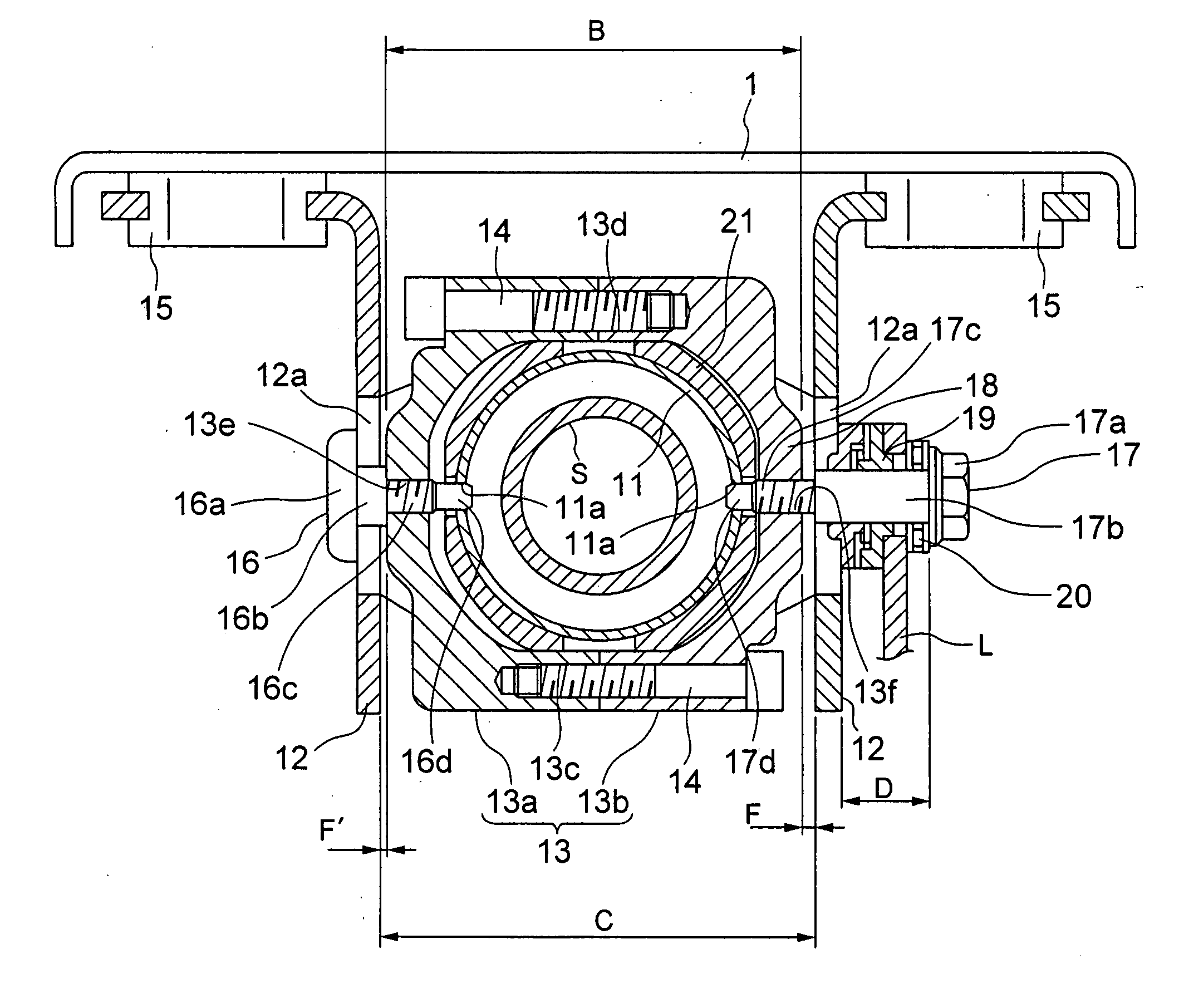
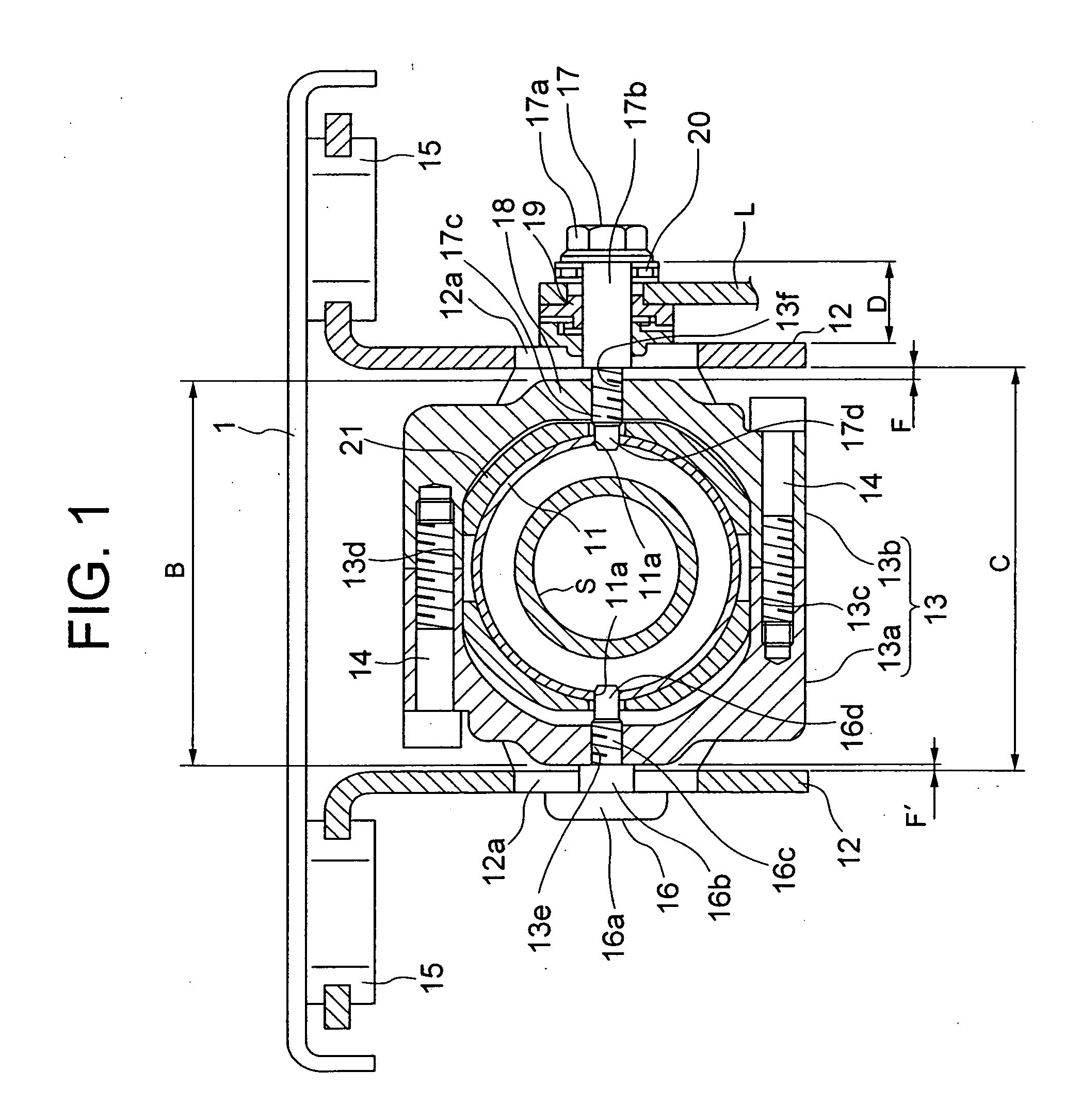
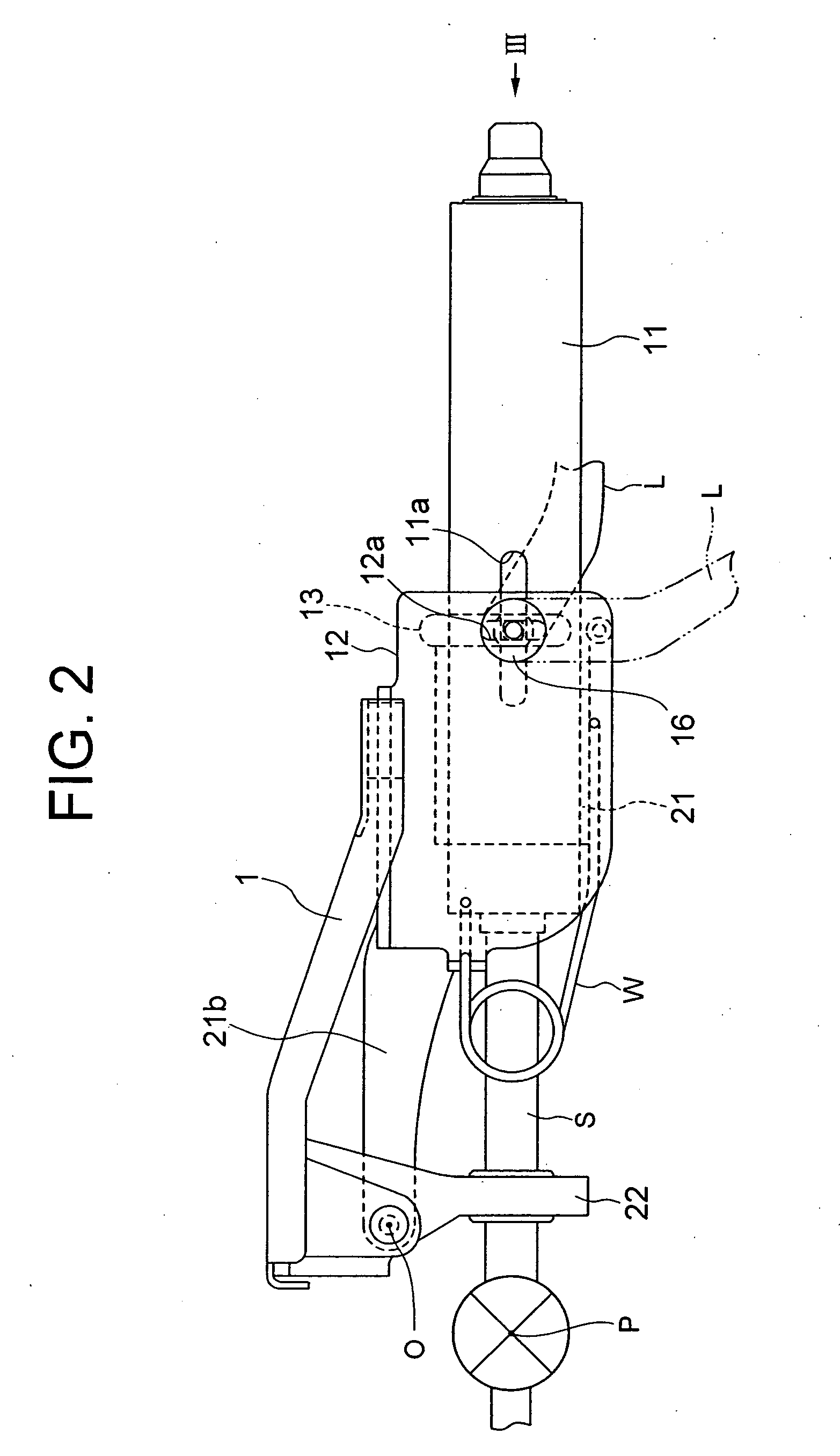
[0030] A tilt / telescopic type steering apparatus according to embodiments of the present invention will hereinafter be described with reference to the drawings. FIG. 1 is a cross-sectional view of the tilt / telescopic type steering apparatus according to the present invention. FIG. 2 is a side view of the steering apparatus shown in FIG. 1. FIG. 3 is a top view of the steering apparatus shown in FIG. 1. FIG. 4 is a view of the steering apparatus shown in FIG. 2 as viewed in an arrowhead-direction III.

[0031] Referring to FIG. 1, two pieces of brackets 12 each composed of a plate material bent in an L-shape, are attached through a pair of release capsules 15 to a top plate 1 secured to an unillustrated car body. A plate thickness of each of the brackets 12 is the same, and the brackets 12 take a configuration exhibiting a line symmetry with respect to a perpendicular line. The release capsule 15, upon a secondary collision, functions such that the release capsule 15 gets collapsed when...

second embodiment

[0049] To describe an adjusting operation of the steering apparatus in the second embodiment, referring to FIG. 5, when the operator (driver) rotates the lever L in the fastening direction, the protruded portions of the first cam member 18 and the second cam member 19 engage with each other, thereby generating forces in such directions as to separate from each other. At this time, the bracket 12 on the right side in FIG. 1, which is pressed by the first cam member 18, gets displaced to the left. While on the other hand, the fixing member 17 pressed rightwards by the second cam member 19 displaces the tension member 13 towards the right. The tension member 13, with this displacement thereof, pushes the flange portions 21c, 21d of the outer column 21 against peripheries of the tilt grooves 12a of the brackets 12 through the friction plates 30, 33, thus giving proper pressing forces. The outer column 21 is thereby fixed to the brackets 12 with the aide of the tremendous frictional forc...

third embodiment

[0053] To give a more specific description about the different point, an outer column 21′ is, as shown in FIG. 8, formed with a screw hole 21f′ in its upper portion. A pin-attached bolt 40 is screwed into this screw hole 21f′ from an outer peripheral side thereof. The pin-attached bolt 40 is formed with a pin portion 40a at its front side end. The pin portion 40a protrudes inwards in a radial direction from an inner peripheral surface of the outer column 21′, and engages with an elongate hole 11c′ formed in an upper portion of the inner column 11′. Note that the inner column 11′ has telescopic holes formed along the peripheries of the fixing members 16, 17 in the

[0054] According to the third embodiment, the outer column 21′ is provided with the pin-attached bolt 40 as the protruded portion extending in the radial direction, and the pin portion 40a engages with the elongate hole 11c′. With this arrangement, when the inner column 11′ and the outer column 21′ get displaced in their axi...


PUM


Abstract

An outer column (21) is held between a tension member (13) and brackets (12) by operating a lever (L), thereby making it possible to block displacements of fixing members (16, 17) along tilt grooves (12a). An inner column (11) is held to the brackets (12) through the outer column (21), whereby the displacements of the fixing members (16, 17) along telescopic grooves (11a) can be blocked. A steering shaft (S) can be thereby fixed in a tilting direction and a telescoping direction. The brackets (12) apply a pressing force to the inner column (11) through flange portions (21c, 21d) of the outer column (21) by operating the lever (L), and the inner column (11) receives the pressing force in a direction opposite to a direction in which the tension member (13) approaches. As rigidities of the pair of brackets (12) are approximately equal, a central position of the inner column (11) can be therefore kept substantially fixed. Hence, an axis deviation of the steering shaft (S) can be effectively restrained.

Description

TECHNICAL FIELD [0001] The present invention relates to a tilt / telescopic type steering apparatus capable of adjusting a tilt angle of a steering wheel and an axis-directional position thereof, corresponding to a driving posture (position) of a driver. BACKGROUND ARTS [0002] What is known as a steering apparatus for an automotive vehicle is a tilt / telescopic type steering apparatus capable of adjusting a tilt angle of a steering wheel and an axis-directional position of the steering wheel, corresponding to a physique and a driving posture of a driver. [0003] In this respect, there is an idea that components of the tilt / telescopic type steering apparatus are disposed as close to a steering shaft as possible in order to ensure a space in the vicinity of knees of the driver. Based on this idea, Japanese Patent Application Laid-Open No. 2001-191927 discloses a steering apparatus constructed such that support members disposed within a steering column are interposed between a pair of brac...

Claims


Application Information

Patent Timeline
IPC IPC(8): B62D1/184B62D1/18B62D1/187
CPCB62D1/187B62D1/184
Inventor IKEDA, SHUHEISATO, KENJI
Owner NSK LTD
Why Eureka
Try Eureka