Deployable antenna with foldable resilient members

a resilient member and antenna technology, applied in the field of antennas, can solve the problems of affecting the operation of the antenna the weight of the system, etc., and the general undesirable effect of excess weight or siz

Active Publication Date: 2005-05-19
THE BOEING CO
View PDF7 Cites 32 Cited by
  • Summary
  • Abstract
  • Description
  • Claims
  • Application Information

AI Technical Summary

Benefits of technology

[0009] In general, the framework of the present invention successfully renders unnecessary many conventional uses of electro-mechanical motors or actuators in deploying various antennas. Furthermore, it is believed that other favorable aspects and advantages of the present invention will become apparent to those skilled in the art upon reading the following detailed description and appended claims and also upon referring to the accompanying drawing figures.

Problems solved by technology

Although such a conventional electro-mechanical system can be effective in successfully deploying a rib-supported reflector antenna, the mechanisms can be heavy and also complex to use and operate.
In particular, such a system with motors, actuators, pulleys, cables, hinges, sliding joints, and the like can be somewhat massive both in terms of weight and size.
Any such excess weight or size is generally undesirable onboard a spacecraft, for it generally necessitates an accommodating increase in launch thrust or launch envelope size.
In addition, such a system can also be complex in terms of both the positioning and the cooperative functioning of its many interrelated parts, thereby giving rise to potential reliability concerns and increases in expenses for components.

Method used


Image

  • Deployable antenna with foldable resilient members
  • Deployable antenna with foldable resilient members
  • Deployable antenna with foldable resilient members

Examples


Embodiment Construction

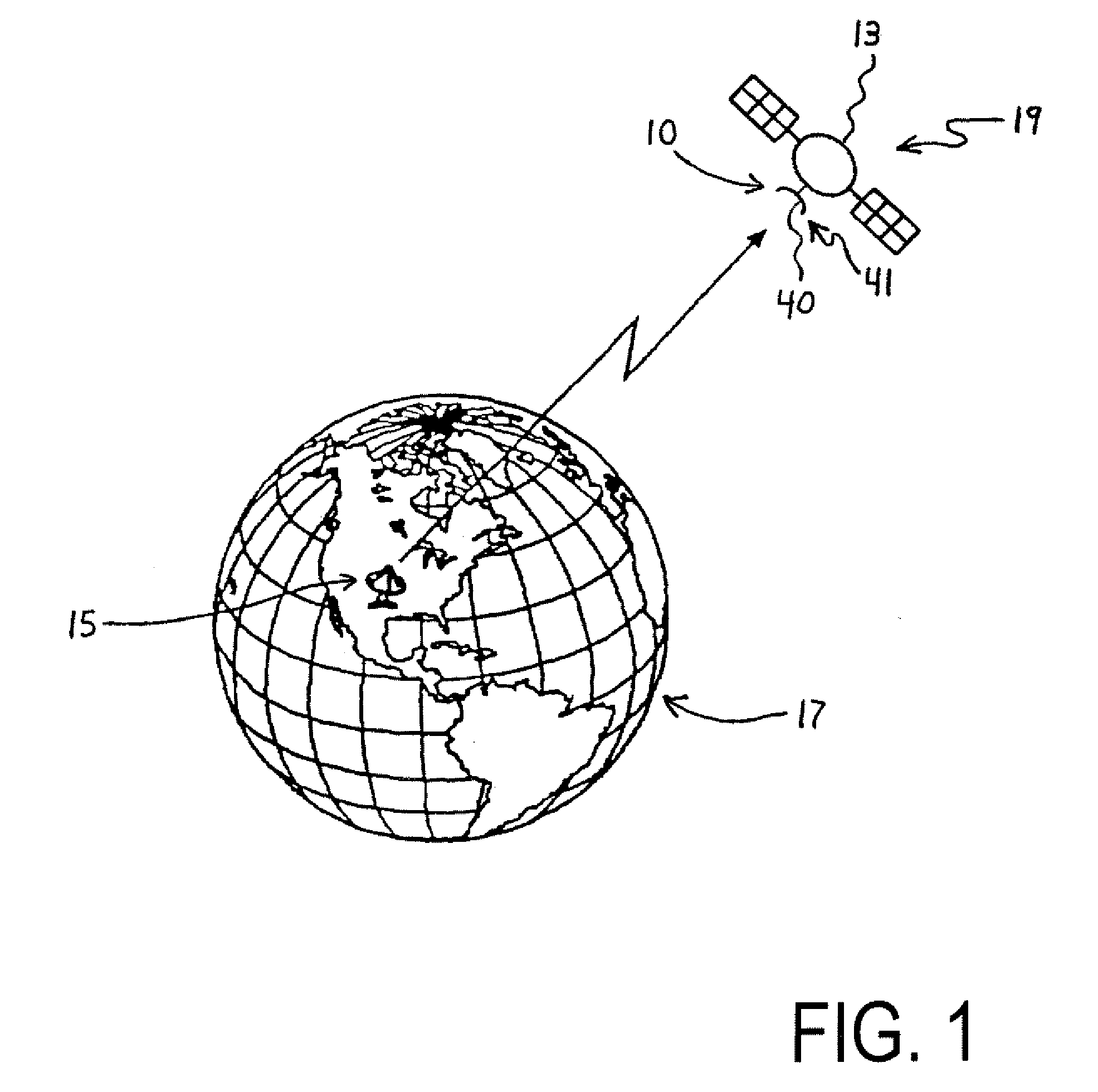
[0022] In FIG. 1, a perspective view of a satellite 19 in orbit about the earth 17 is illustrated. The satellite 19 itself includes both a fuselage or body 13 and a deployable mesh reflector type antenna 41 mounted thereon. The deployable antenna 41, in turn, includes both a reflective mesh 40 and a supportive framework 10 for deploying and suspending the mesh 40. In having the deployable antenna 41 onboard, the satellite 19 is able to send and receive electromagnetic waves for thereby communicating with, for example, a ground communications station 15 while the satellite 19 is in orbit in outer space.

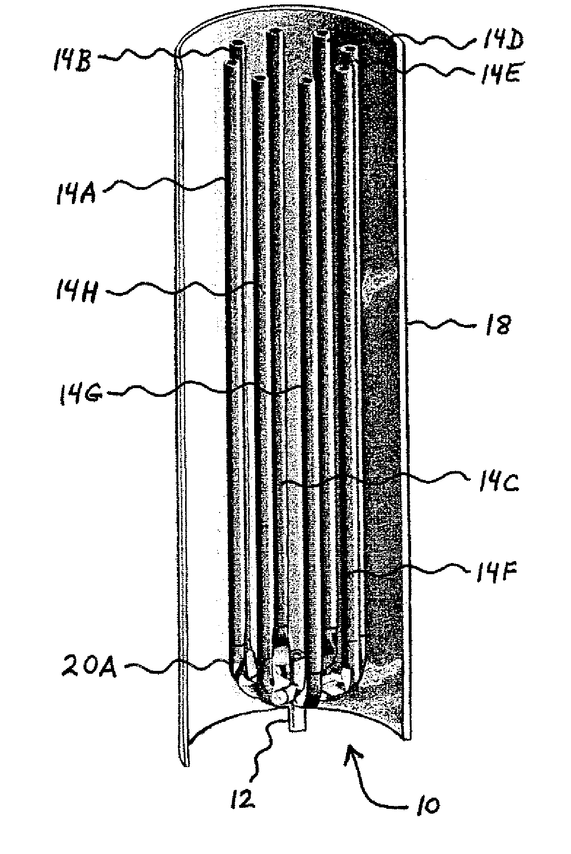
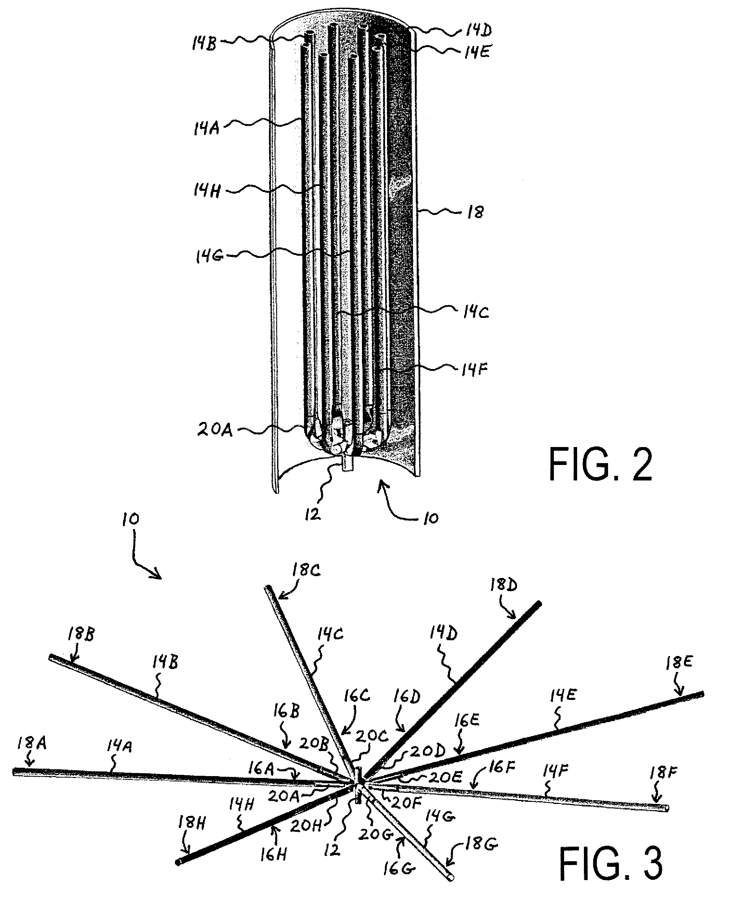
[0023] In FIGS. 2 and 3, perspective views of the framework 10 for the deployable mesh reflector type antenna 41 are illustrated therein. As illustrated, the framework 10 basically includes a hub 12, a plurality of elongate ribs 14, and a matching plurality of foldable resilient members 20. In the particular embodiment of the framework 10 illustrated in FIGS. 2 and 3, the plurality of...


PUM


Abstract

A framework for a deployable antenna is disclosed herein. The framework basically includes a plurality of elongate ribs, a matching plurality of foldable resilient members, and a hub. Each of the elongate ribs has both a proximal end and a distal end. The foldable resilient members serve to interconnect the proximal ends of the elongate ribs to the hub. Within such a configuration, each of the foldable resilient members is capable of storing strain energy whenever forcibly folded and also releasing the strain energy whenever subsequently permitted to elastically unfold. Thus, whenever the elongate ribs are released from a stowed position in which the foldable resilient members are forcibly folded, the strain energy causes automatic deployment of the antenna as the foldable resilient members are permitted to elastically unfold. In sum, therefore, the framework obviates many conventional uses of electro-mechanical motors or actuators in deploying various antennas.

Description

BACKGROUND OF INVENTION [0001] The present invention generally relates to antennas that are mounted and employed onboard, for example, spacecraft or satellites. The present invention more particularly relates to frameworks or systems for deploying such onboard antennas while the spacecraft or satellites are in outer space. [0002] Reflector antennas are commonly mounted and employed onboard spacecraft for sending and receiving electromagnetic waves within the radio frequency (RF) spectrum for communicative purposes while the spacecraft are in outer space. Although different types of reflector antennas may be utilized for such purposes, a commonly used antenna is a rib-supported reflector antenna. In a rib-supported reflector antenna, a framework or system of ribs is utilized to suspend, shape, and position a flexible mesh or screen made of RF energy reflective material. One significant advantage in utilizing such a rib-supported reflector antenna is that large-aperture antennas with ...

Claims


Application Information

Patent Timeline
Patent Type & Authority Applications(United States)
IPC IPC(8): H01Q1/08H01Q1/12H01Q1/28H01Q15/16
CPCH01Q1/08H01Q15/161H01Q1/288H01Q1/1235
Inventor NOLAN, MICHAELBASSILY, SAMIR F.GEHLE, RICHARD W.LAKE, JERRY MILES
Owner THE BOEING CO
Why Eureka
Try Eureka