Method of camouflaging defective print elements in a printer

a technology of defective print elements and printers, applied in the field of camouflage of defective print elements in printers, can solve the problems of image information loss, defective nozzles, degraded print quality, etc., and achieve the effect of camouflage of image defects

Active Publication Date: 2005-05-19
OCE TECH
View PDF5 Cites 24 Cited by
  • Summary
  • Abstract
  • Description
  • Claims
  • Application Information

AI Technical Summary

Benefits of technology

[0009] It is an object of the invention to provide a method which permits to camouflage image defects, that would otherwise be caused by defective print elements, efficiently.
[0018] It is one of the advantages of the invention that the process of shifting image information from the defective nozzle to non-defective nozzles provides more flexibility because it is carried out on the level of the multi-level pixel matrix where the ratios or weights with which the grey level is distributed onto neighbouring pixels can be varied so as to achieve optimal results. Another advantage is that the method according to an aspect of the invention is carried out at a comparatively early stage in the processing sequence, so that the method can also be adapted, for example, to printer hardware which has no sufficient processing capability for carrying out corrections on bitmap level. It is even possible that the method according to an aspect of the invention is executed in a host computer from which the print data are sent to the printer, provided that the information, indicating which nozzles are defective, is made available at the host computer. Then, if the printer forms part of a multi-user network, the data processing necessary for carrying out the invention may be distributed over a plurality of computers in the network. Moreover, the data processing for transferring the grey levels to neighbouring pixels may advantageously be combined with other image processing steps that have to be performed on multi level-data, such as gamma correction and the like.
[0019] Depending on the algorithm employed for converting the multi-level data into binary data, such as error diffusion or dithering, the invention will also increase the likelihood that the black pixels that cannot be printed are actually shifted to empty pixel positions in the neighbourhood rather than being lost.
[0020] When the multi-level data are converted into binary data, it is preferable to employ an algorithm which makes sure that the extra black pixels are not shifted back to positions where they cannot be printed. An error diffusion algorithm is considered to be particularly useful. If, for example, the error is diffused or propagated only in the direction of the pixel lines but not towards neighbouring lines, or in any case not towards the line that is assigned to the defective nozzle, the loss of image information can successfully be avoided. As an alternative, the error diffusion process may be adapted such that pixel positions which cannot be printed are skipped in the error diffusion process.

Problems solved by technology

When a nozzle of the printhead is defective, e.g., it has become clogged, the corresponding pixel line is missing in the printed image, so that image information is lost and the quality of the print is degraded.
In this case, it is in some cases possible that a defective nozzle is backed-up by a non-defective nozzle, though mostly on the cost of productivity.
However, if this neighbouring pixel position happens to be occupied by a black pixel, anyway, pursuant to the original print data, then the extra pixel cannot be printed, and a loss of image information will nevertheless occur.

Method used


Image

  • Method of camouflaging defective print elements in a printer
  • Method of camouflaging defective print elements in a printer
  • Method of camouflaging defective print elements in a printer

Examples


Embodiment Construction

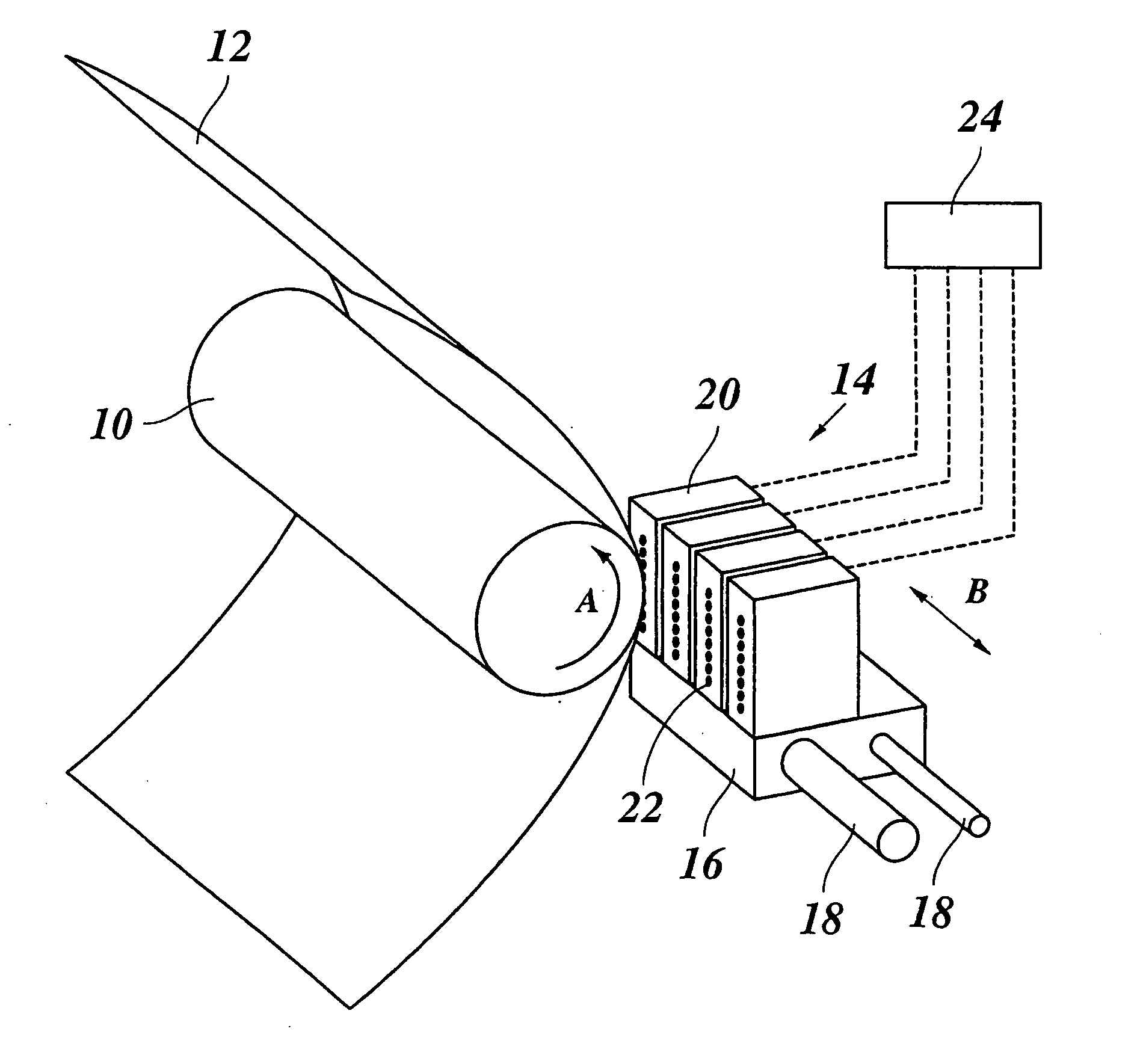
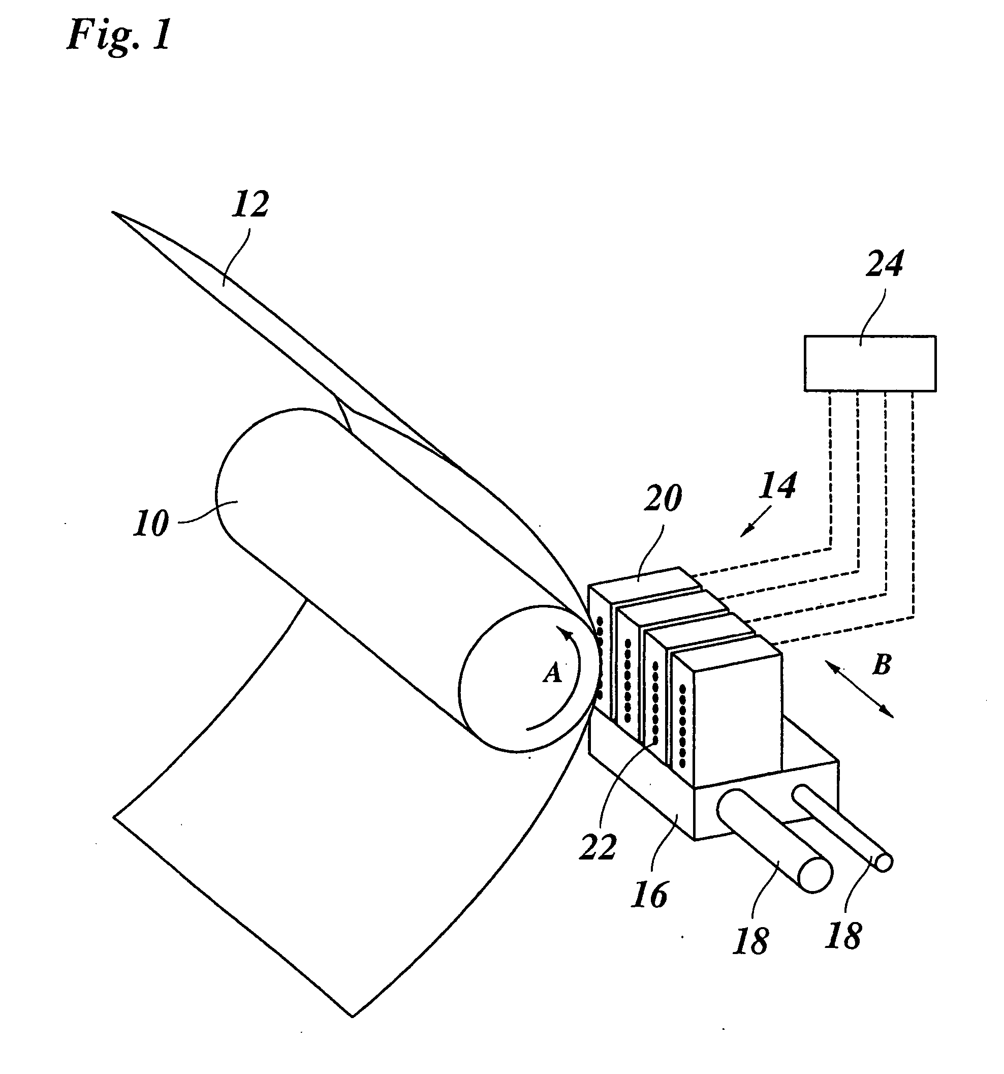
[0030] As is shown in FIG. 1, an ink jet printer comprises a platen 10 which serves for transporting a recording paper 12 in a subscanning direction (arrow A) past a printhead unit 14. The printhead unit 14 is mounted on a carriage 16 that is guided on guide rails 18 and is movable back and forth in a main scanning direction (arrow B) relative to the recording paper 12. In the example shown, the printhead unit 14 comprises four printheads 20, one for each of the basic colours, e.g., cyan, magenta, yellow and black. Each of the printheads 20 has a linear array of nozzles 22 extending in the subscanning direction. The nozzles 22 of the printheads 20 can be energized individually to eject ink droplets onto the recording paper 12, thereby to print a pixel on the paper 12. When the carriage 16 is moved in the direction B across the width of the paper 12, a swath of an image can be printed. The number of pixel lines of the swath corresponds to the number of nozzles 22 of each printhead. W...


PUM


Abstract

A printer, a computer program and a method are provided for camouflaging defective print elements in the printer having a printhead with a plurality of print elements. The method includes (a) representing the image information to be printed by a multi-level pixel matrix wherein a grey level of each pixel is indicated by a number, (b) transferring the grey levels of pixels that are assigned to a defective print element, to neighbouring pixels in the pixel matrix, and (c) converting the pixel matrix having the transferred grey levels, into a bitmap to be printed.

Description

[0001] The present application claims, under 35 U.S.C. § 119, the benefit of European Patent Application No. 03078482.1 filed Nov. 5, 2003, the entire contents of which are herein fully incorporated by reference. BACKGROUND OF THE INVENTION [0002] 1. Field of the Invention [0003] The invention relates to a method of camouflaging defective print elements in a printer having a printhead with a plurality of print elements and capable of printing a binary pixel image, wherein each pixel of the image is assigned to a print element with which it is to be printed, and image information of a pixel that is assigned to a defective print element is shifted to nearby pixel positions where it can be printed by a non-defective print element. The invention further relates to a printer and to a computer program implementing this method. The invention is applicable, for example, to an ink jet printer, the printhead of which comprises a plurality of nozzles as print elements. [0004] 2. Discussion of ...

Claims


Application Information

Patent Timeline
Patent Type & Authority Applications(United States)
IPC IPC(8): B41J2/01B41J2/165B41J2/21B41J2/505B41J2/52G06F15/00G06F17/00G06K15/10
CPCB41J2/505B41J2/2139
Inventor VESTJENS, JOHANNES C.G.FAKEN, HENRY
Owner OCE TECH
Why Eureka
Try Eureka