Reaction Apparatus, Fuel Cell System and Electronic Device

a fuel cell and reaction apparatus technology, applied in the direction of electrochemical generators, ceramic layered products, sustainable manufacturing/processing, etc., can solve the problems of large heat propagation from the reformer, the number of faces at which the catalyst comes into contact is small, and the reactor cannot be heated quickly to a uniform temperature, etc., to achieve the effect of superior thermal conductivity, efficient cause of reaction, and thermal conductivity of the connecting portion

Inactive Publication Date: 2010-04-08
KYOCERA CORP +1
View PDF16 Cites 8 Cited by
  • Summary
  • Abstract
  • Description
  • Claims
  • Application Information

AI Technical Summary

Benefits of technology

[0045]According to the invention, fins having superior thermal conductivity are provided, so that a fluid that passes through the reaction portion is heated easily. Also, because the heat generating portion includes a first ceramic part, heat is not easily dissipated except at the fins, and as a result, it is possible to efficiently cause a reaction.
[0046]According to the invention, because the thermal conductivity of the connecting portion is lower than that of the side wall of at least one of the high temperature reaction chamber and the low temperature reaction chamber, heat, propagation between the high temperature reaction chamber and the low temperature reaction chamber can be suppressed to a relatively low level. In addition, at least one of the high temperature reaction chamber and the low temperature reaction chamber has the side wall that defines a flow channel and includes a second member having a thermal conductivity higher than the connecting portion, so that the inside of the reaction chamber can be heated to a uniform temperature rapidly.
[0047]According to the invention, it is possible to suppress heat transfer between the high temperature reaction portion and the low temperature reaction portion.
[0048]According to the invention, the fuel cell can generate power using a reaction product produced by the reaction apparatus as fuel, and, as such, a raw material that is easier to handle than the gaseous fuel supplied to the fuel cell can be caused to react in the reaction apparatus, and the resulting reaction product can be used as fuel in the fuel cell. Therefore, power can be generated in the fuel cell by storing a raw material that is easier to handle than gaseous fuel, and, thus, an easy-to-handle fuel cell system can be achieved.
[0049]According to the invention, it is possible to achieve an electronic device that is driven with power generated by the fuel cell system.
[0050]According to the invention, it is possible to generate and supply the power required by the operating portion, the display portion and the operation control portion with the fuel cell system. Consequently, an electronic device that is driven with power generated by the fuel cell system can be achieved.

Problems solved by technology

Accordingly, there arises a problem that the number of faces at which the catalyst comes into contact is small among faces that define a flow channel.
However, when configuring a reformer, a CO remover, and a connecting pipe for connecting the reformer and the CO remover using a material having low thermal conductivity, a problem arises that the reactors cannot be heated quickly to a uniform temperature.
However, the appropriate reaction temperature of the carbon monoxide remover is usually lower than that of the reformer, so that heat is excessively propagated from the reformer to the carbon monoxide remover and cooling the reformer, or excessively heating the carbon monoxide remover.
Accordingly, it is not at all easy to appropriately control reaction temperatures particularly for a small-scale reformer and carbon monoxide remover.

Method used


Image

  • Reaction Apparatus, Fuel Cell System and Electronic Device
  • Reaction Apparatus, Fuel Cell System and Electronic Device
  • Reaction Apparatus, Fuel Cell System and Electronic Device

Examples


Embodiment Construction

[0067]Now referring to the drawings, preferred embodiments of the invention are described below.

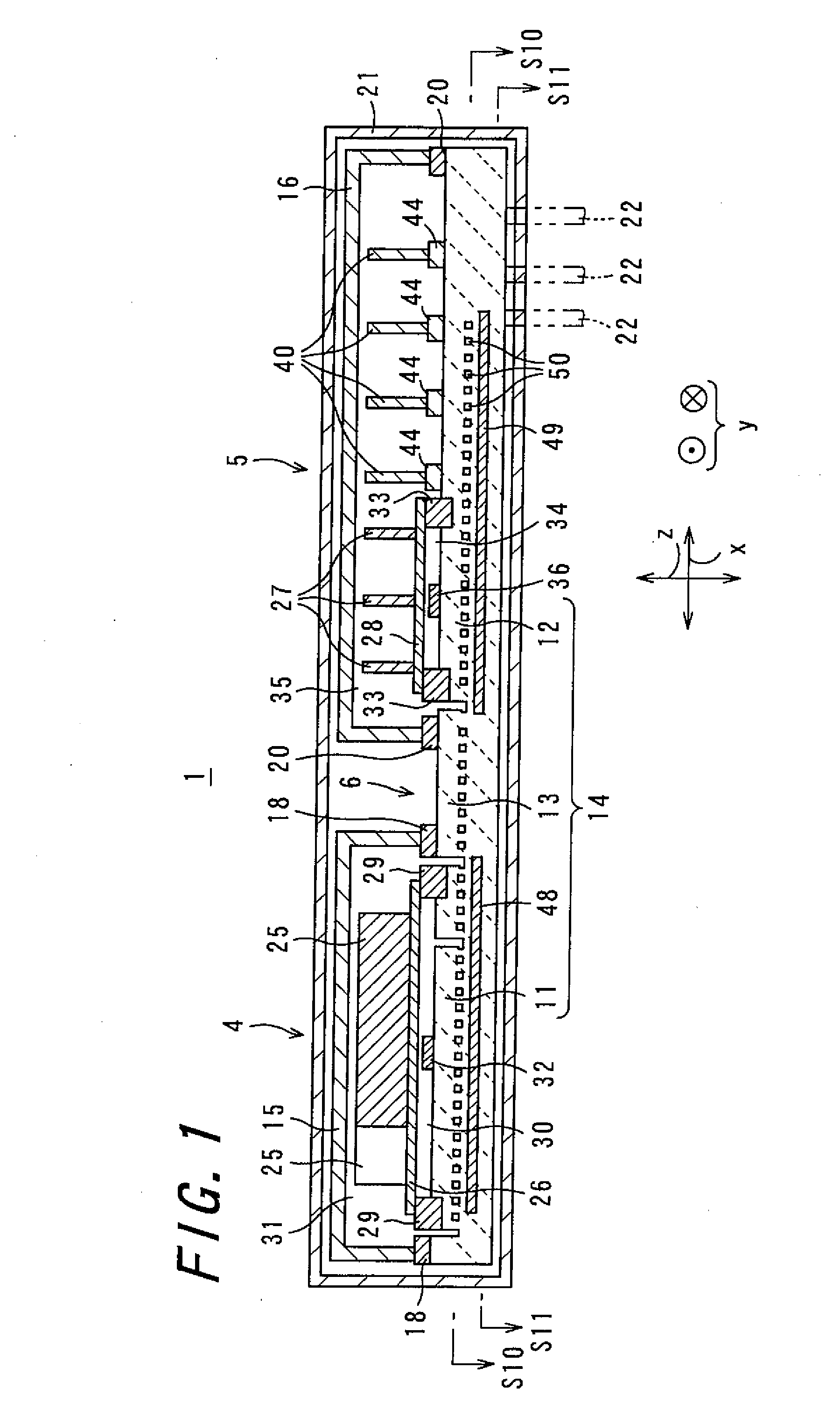
[0068]FIG. 1 is a cross-sectional view of a reaction apparatus 1 according to an embodiment of the invention.

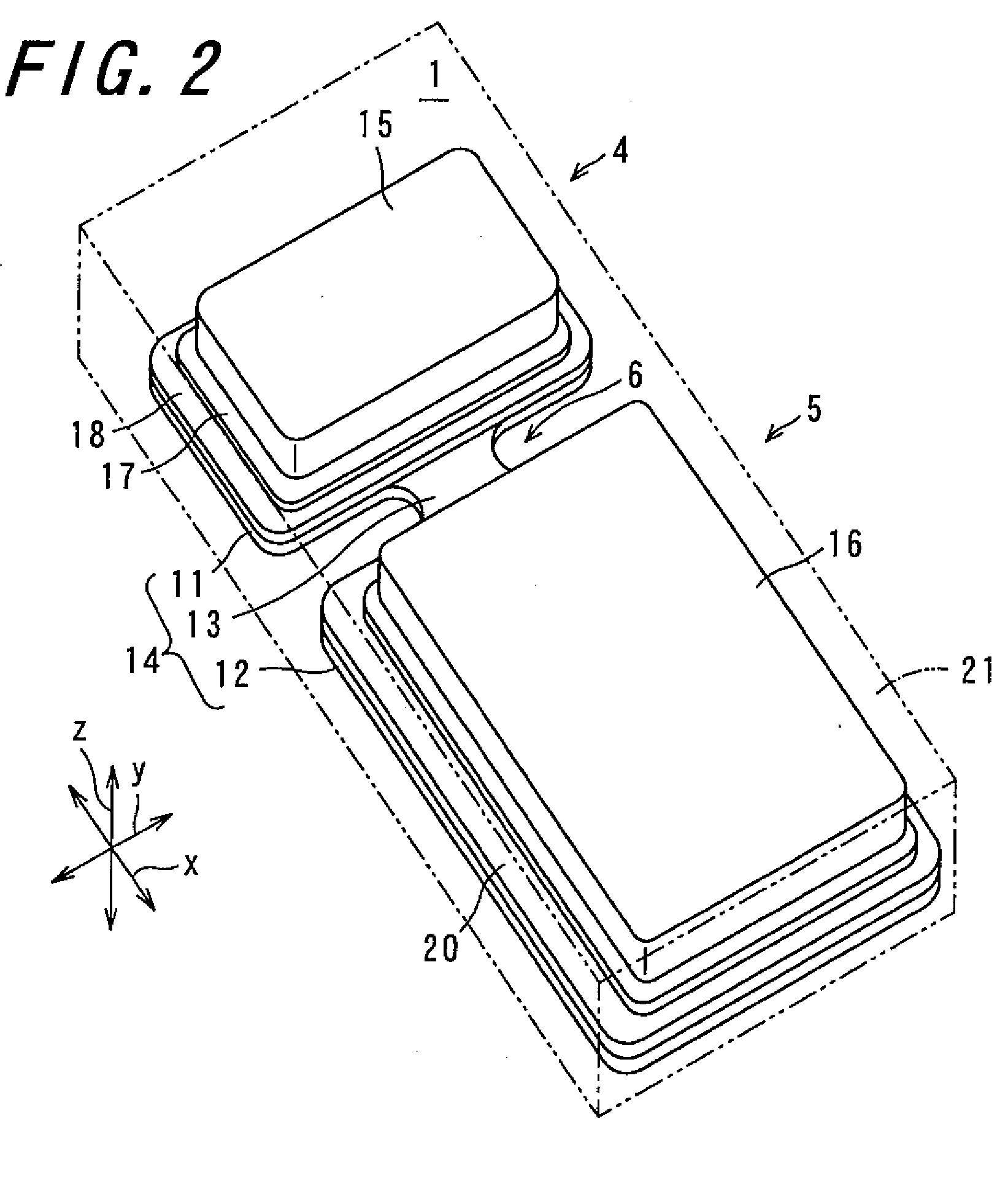
[0069]FIG. 2 is a perspective view of the reaction apparatus 1.

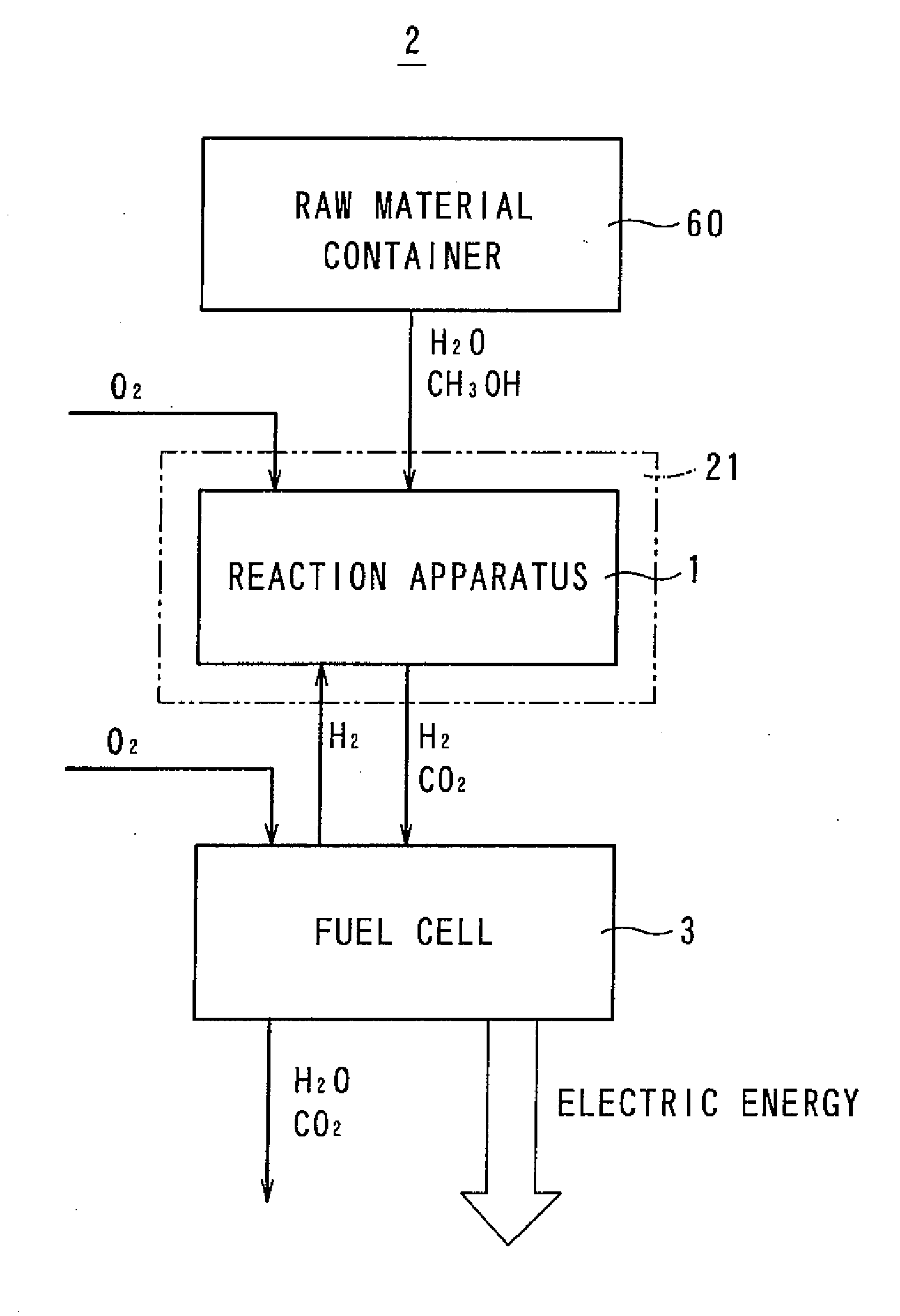
[0070]FIG. 3 is a block diagram of a fuel cell system 2 that includes the reaction apparatus 1. The reaction apparatus 1 is an apparatus for generating a reaction product by the chemical reaction of a raw material. In the present embodiment, the reaction apparatus 1 is included in the fuel cell system 2, and is used as a reforming apparatus for generating a fuel utilized by a fuel cell 3 for power generation.

[0071]The reaction apparatus 1 includes a reformer 4 serving as a high temperature reaction portion that generates hydrogen gas by reforming a fuel having a compound containing hydrogen in its composition, a carbon monoxide remover (hereinafter referred to as “CO remover”) 5 serving as a low temperature reaction por...


PUM

PropertyMeasurementUnit
pressureaaaaaaaaaa
thermal conductivityaaaaaaaaaa
temperatureaaaaaaaaaa

Abstract

The invention provides a reaction apparatus capable of efficiently causing a reaction, and a fuel cell system and an electronic device that include such a reaction apparatus. A reaction apparatus (1) includes a reformer (4), a CO remover (5) and a connecting portion (6) that connects the reformer (4) and the remover (5). The reformer (4) has a reforming reaction chamber (31) and a reformer combustion chamber (30) that generates heat to be supplied to the reforming reaction chamber (31), which (30, 31) are adjacent to each other with a partition interposed therebetween. The CO remover (5) has a removing reaction chamber (35) and a remover combustion chamber (34) that generates heat to be supplied to the removing reaction chamber (35), which (34, 35) are adjacent to each other with a partition interposed therebetween. The reformer (4) and the CO remover (5) are arranged spaced apart from each other, at least one of which is configured by combining ceramic parts (11, 12) and a reformer lid member (15) and a remover lid member (16), and heaters (48, 49) are disposed so as to face the ceramic parts (11, 12).

Description

TECHNICAL FIELD[0001]The present invention relates to a reaction apparatus, a fuel cell system comprising such a reaction apparatus, and an electronic device comprising such a fuel cell system.BACKGROUND ART[0002]Fuel cells, which generate electric energy through an electrochemical reaction between oxygen and hydrogen, are used in automobiles and portable devices as a clean power source having a high energy conversion efficiency. Because hydrogen is difficult to handle, in a certain type of fuel cell, stored hydrogen is not supplied thereto, but instead, an alcohol or hydrocarbon stored is reacted so that a gas composed mainly of hydrogen is generated, and the generated gas is supplied to the fuel cell. A reaction apparatus is used to generate the gas composed mainly of hydrogen.[0003]A conventional reaction apparatus is disclosed in, for example, Japanese Unexamined Patent Publication JP-A 2004-356003. The reaction apparatus disclosed in JP-A 2004-356003 includes a reforming portio...

Claims


Application Information

Patent Timeline
Patent Type & Authority Applications(United States)
IPC IPC(8): H01M8/18B01J19/00
CPCB01J8/0438C04B2237/76B01J8/0492B01J8/0496B01J2208/00309B01J2208/00495B01J2208/00716B01J2219/00768B01J2219/1923B32B18/00C01B3/384C01B2203/0227C01B2203/044C01B2203/047C01B2203/066C01B2203/0811C01B2203/0822C01B2203/0827C01B2203/1035C01B2203/1047C01B2203/1064C01B2203/107C01B2203/1076C01B2203/1604C04B2237/343C04B2237/366C04B2237/62H01M8/0631Y02E60/50C04B37/026C04B2237/12C04B2237/123C04B2237/406B01J8/0442Y02P20/10
Inventor YAMAMOTO, TADAOSAITO, KAORUMIYAMOTO, NAOTOMOSHIOYA, MASAHARUMORI, RYUJIMIYAUCHI, MASAHIKOMIYAHARA, MASAAKIBASHO, YOSHIHIROHASHIMOTO, TOSHIHIROOGASAWARA, ATSUSHI
Owner KYOCERA CORP
Why Eureka
Try Eureka