Moving picture coding method and decoding method, and apparatus and program using the same

a technology of moving picture and coding method, which is applied in the field of moving picture encoding/decoding program, can solve the problems of limiting the bandwidth of the input image, not directly improving the encoding efficiency of the motion picture, and methods of the prior art are incapable of decimal point picture element interpolation that accords with bit rate and the nature of the moving picture, so as to improve the effect of motion compensation and improve encoding efficiency

Active Publication Date: 2005-05-19
NEC CORP
View PDF6 Cites 50 Cited by
  • Summary
  • Abstract
  • Description
  • Claims
  • Application Information

AI Technical Summary

Benefits of technology

[0014] The present invention was realized in view of the above-described prior art and has an object the provision of a method of encoding / decoding a moving picture that can enhance the effect of motion compensation and improve encoding efficiency.

Problems solved by technology

A prefilter limits the bandwidth of the input image, and therefore does not directly improve the encoding efficiency of a motion picture.
As a consequence, the methods of the prior art are incapable of decimal point picture element interpolation that accords with bit rate and the nature of the moving picture.

Method used


Image

  • Moving picture coding method and decoding method, and apparatus and program using the same
  • Moving picture coding method and decoding method, and apparatus and program using the same
  • Moving picture coding method and decoding method, and apparatus and program using the same

Examples


first embodiment

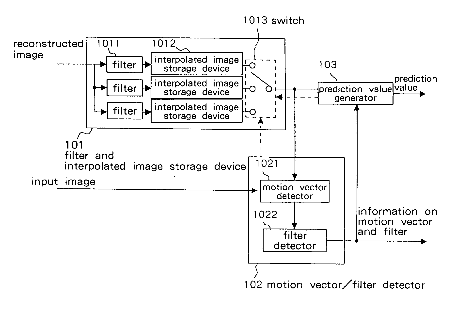
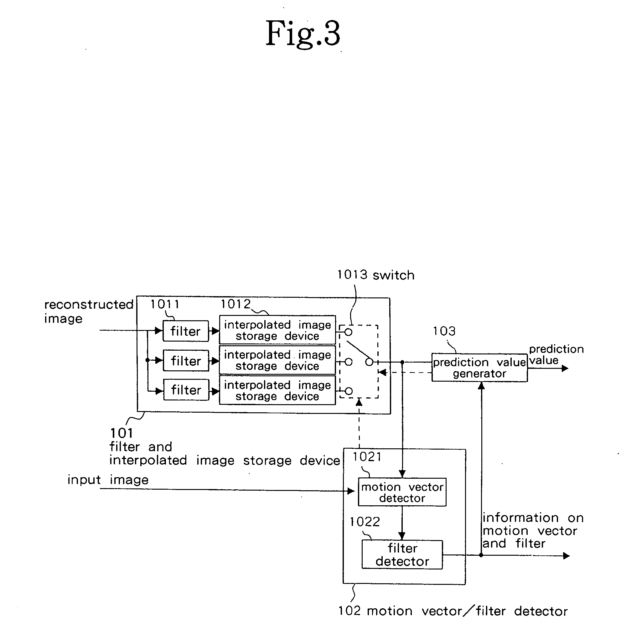
[0052]FIG. 3 is a block diagram showing the configuration of the first embodiment of the present invention. The present embodiment is realized by using a typical computer system that is made up of a control device, a storage device, an input device, and a display device. FIG. 3 shows only the principal components of the embodiment.

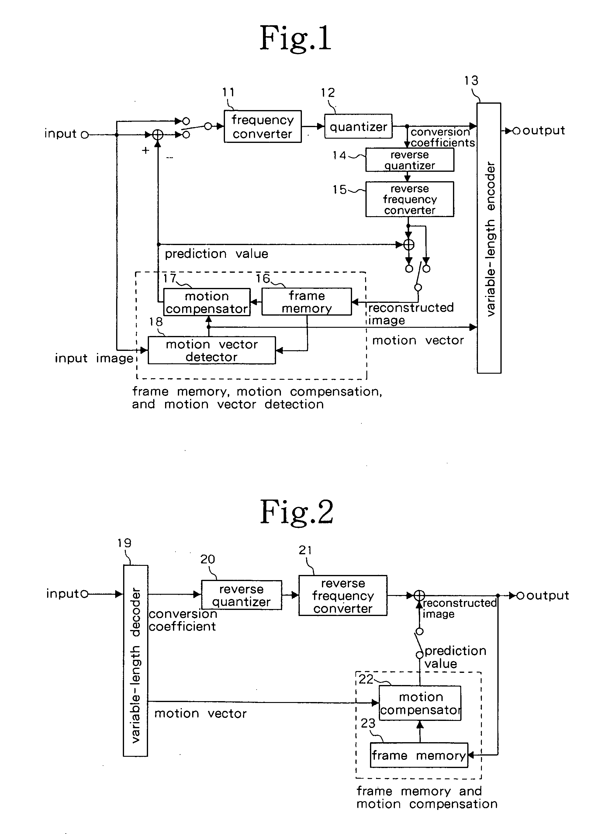
[0053] The embodiment includes filter / interpolated image storage device 101, motion vector / filter coefficient detector 102, and prediction value generator 103. These components correspond to the frame memory / motion compensation / motion vector detection of the encoding method that was shown in FIG. 1, and components other than these have the same composition as the encoding devices shown in FIG. 1. The following explanation of the present embodiment therefore also makes reference to FIG. 1.

[0054] The present embodiment is constructed for a case in which the main memory of a computer system that includes the present embodiment has a surplus and can store a ...

second embodiment

[0079] The second embodiment of the present invention is next explained. The present embodiment is constructed for a case in which the main memory of the computer system that includes the present embodiment has no surplus and is unable to store a plurality of interpolated images. The configuration and operation of this embodiment are described hereinbelow.

[0080]FIG. 5 is a block diagram showing the main configuration of the second embodiment of the present invention.

[0081] The present embodiment is provided with filter / interpolated image storage device 101b, motion vector / filter coefficient detector 102b, and prediction value generator 103b. Compared with the constituent elements of the embodiment that is shown in FIG. 3, filter / interpolated image storage device 101b performs the same operation as filter / interpolated image storage device 101; motion vector / filter coefficient detector 102b performs the same operation as motion vector / filter coefficient detector 102; and prediction ...

third embodiment

[0086] The following explanation regards the third embodiment of the present invention. The present embodiment is constructed for a case in which the main memory of the computer system that includes the present embodiment has no surplus in decoding and cannot store decimal point position interpolated images. The configuration and operation of the present embodiment are as described hereinbelow.

[0087]FIG. 7 is a block diagram showing the principal configuration of the present embodiment. The present embodiment includes filter switching device 201 and prediction value generator 202. These components correspond to the frame memory / motion compensator / motion vector detection of the encoding system that is shown in FIG. 1, and constituent elements other than these components are of the same construction as the encoder shown in FIG. 1. The following explanation of the present embodiment therefore also makes reference to FIG. 1.

[0088] Filter switching device 201 switches the filter coeffi...


PUM


Abstract

The present invention seeks to provide a solution to the problem that motion compensation in an encoding method of the prior art involves decimal point picture element interpolation by means of fixed filters and therefore cannot realize interpolation of decimal point picture elements that accords with the nature and bit rate of a moving picture. A filter/interpolated image memory (101) interpolates picture elements of decimal point positions in a reference image by means of a plurality of sets of filters, a motion vector, filter detector (102) detects the combination of filter and motion vector that realizes the highest encoding efficiency, a prediction value generator (103) uses the detected combination of filter and motion vector to generate a prediction value, and motion vector/filter detector (102) supplies as output the information of the filter and information of the motion vector that generated the prediction value; whereby decimal point picture element interpolation that corresponds to the nature and bit rate of the moving picture can be realized and encoding of a moving picture can be improved.

Description

BACKGROUND OF THE INVENTION [0001] 1. Field of the Invention [0002] The present invention relates to a moving picture encoding and decoding method, and in particular, relates to a moving picture encoding / decoding program, method, and device in which filter coefficients are adaptively switched to encode the interpolation of decimal-point picture elements used in motion compensation. [0003] 2. Description of the Related Art [0004] In digital broadcast systems or services, a large number of moving picture signals are compressed and encoded for transmission and storage. [0005]FIG. 1 is a block diagram showing the configuration of a typical encoding device for moving picture signals. The encoding device that is shown in FIG. 1 includes a local decoder and is made up of: frequency converter 11, quantizer 12, variable-length encoder 13, reverse quantizer 14, reverse frequency converter 15, frame memory 16, motion compensator 17, and motion vector detector 18. [0006] An input image is appli...

Claims


Application Information

Patent Timeline
Patent Type & Authority Applications(United States)
IPC IPC(8): G06T9/00H04N19/51H03M7/36H04N19/103H04N19/117H04N19/132H04N19/139H04N19/172H04N19/196H04N19/423H04N19/50H04N19/503H04N19/523H04N19/59H04N19/80
CPCH04N19/105H04N19/176H04N19/172H04N19/46H04N19/523H04N19/61H04N19/117H04N19/82H04N19/149H04N19/51H04N19/80
Inventor CHONO, KEIICHI
Owner NEC CORP
Why Eureka
Try Eureka