Reader for conducting assays

a technology of reading device and conducting assay, which is applied in the direction of color/spectral property measurement, material analysis, instruments, etc., can solve the problems of complicated temperature control, limited operation lifetime, and large amount of heat, so as to reduce the net weight of the device, reduce the power demand of the device, and reduce the calibration demand of the operation.

Inactive Publication Date: 2005-05-19
ASSOCS OF CAPE COD
View PDF22 Cites 45 Cited by
  • Summary
  • Abstract
  • Description
  • Claims
  • Application Information

AI Technical Summary

Benefits of technology

[0009] Another object of this invention is to provide a novel method and device that, in one embodiment, allows a user to simultaneously assay both turbidity and chromogenic reactions in plural vessels.
[0017] Other embodiments of such devices can include a precalibrated temperature transducer that reduces calibration demands for operating such a device.

Problems solved by technology

Incandescent light sources are however only suitable for performing certain types of assays since their emission intensity is primarily in the IR and long wavelength portion of the visible spectrum.
Moreover, incandescent light sources require intensity adjustments to maintain a relatively constant emission flux, have limited operational lifetimes, and, as a consequence of resistive heating of the filament, dissipate large amounts of heat that often complicate temperature control in incubators.
Finally, since incandescent sources require relatively large amounts of power, they are commonly driven by high power AC sources such as line sources and microcontroller-based modulation of incandescent source intensity is relatively difficult to implement.
As both the light transduction and light generation described by Noeller (U.S. Pat. No. 4,784,947) only occurs at discrete times, continuous monitoring and automated data analysis is not possible.

Method used


Image

  • Reader for conducting assays
  • Reader for conducting assays
  • Reader for conducting assays

Examples


Embodiment Construction

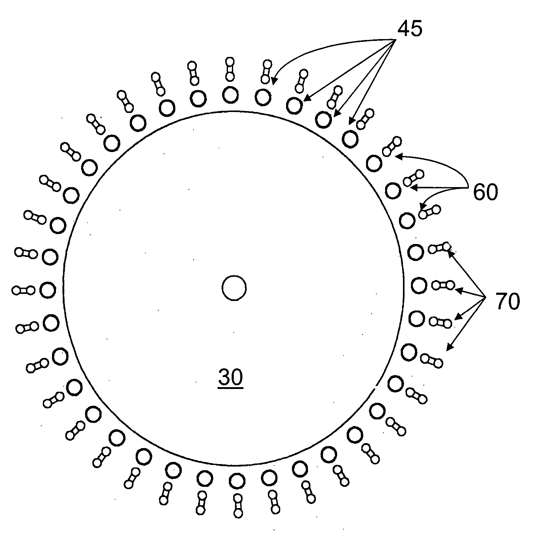
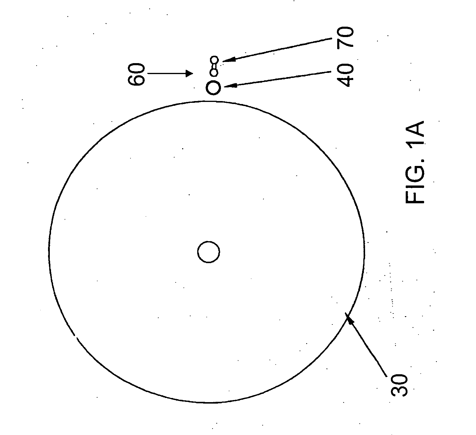
[0036] Referring now to the drawings, wherein like reference numerals designate identical or corresponding parts throughout the several views, and more particularly to FIG. 1 thereof, which illustrates an exemplary optical system according to the present invention. The illustrated optical system generates light, radially guides it to one or more vessels containing an analyte, transmits the light through the vessel and / or the analyte, and then pipes the light to one or more light transducers where it is transduced. As used herein, radial guiding refers to the transmission of light to plural vessels along plural optical paths, wherein the transmittance along the various paths is substantially equal. This situation is possible to implement using a circular (or arcular) waveguide with a source located at the center, hence giving rise to the term “radial guiding.”

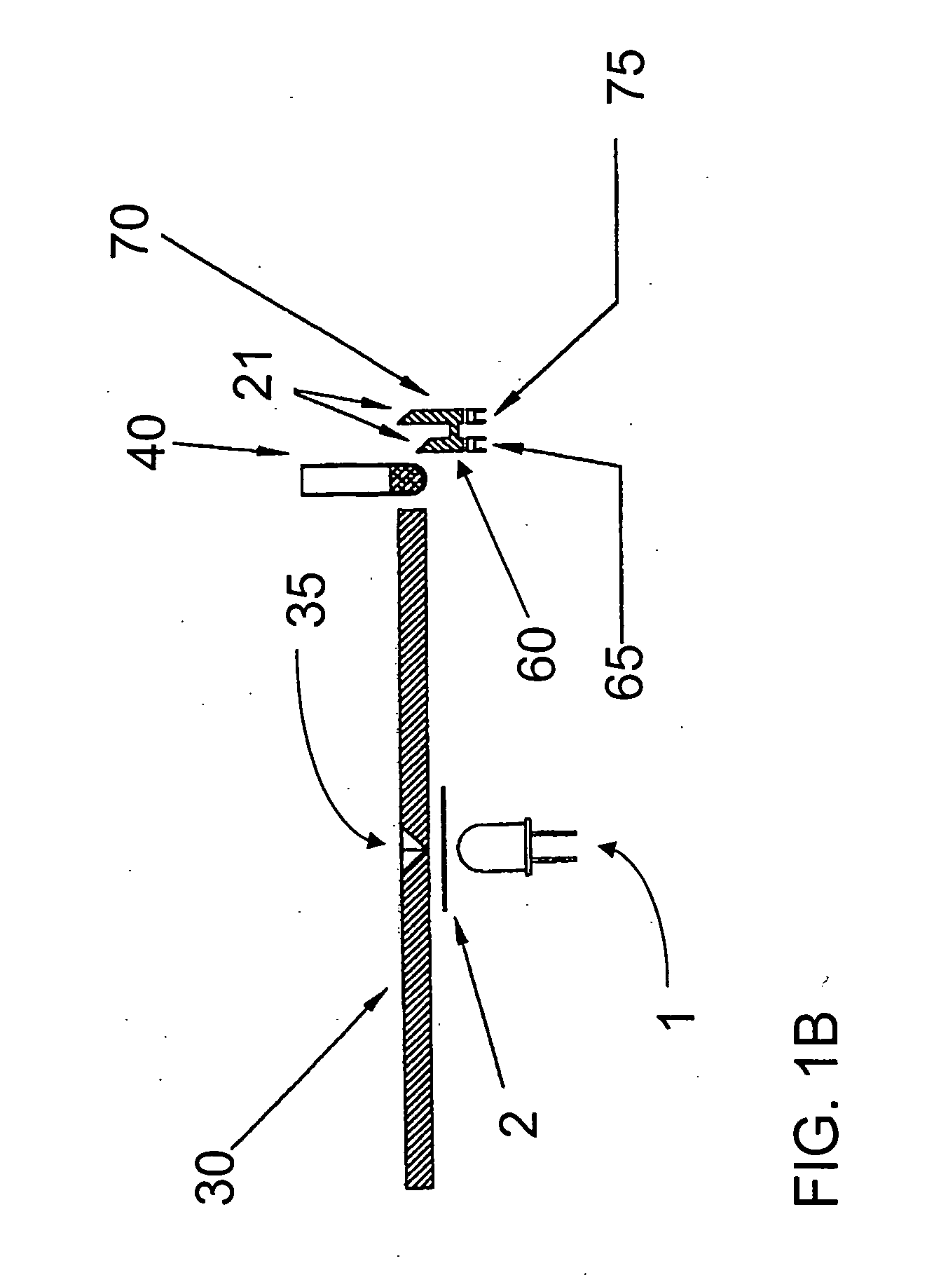
[0037] In FIGS. 1A and 1B, LED source 1 generates and emits photons, and can also optionally serve to collimate and / or focus t...


PUM

PropertyMeasurementUnit
center wavelengthaaaaaaaaaa
temperatureaaaaaaaaaa

Abstract

An analytical device that can be used to conveniently and accurately assay plural vessels. In one exemplary embodiment, a pair of LED sources provides illumination through a pair of radial waveguides to plural vessels arranged in a pair of substantially concentric and circular rows about the LED sources. A light pipe receives light transmitted through a vessel from each radial waveguide and reflects the received light downward to a single printed circuit board that contains a photodiode for each light pipe, as well as processing circuitry. The first LED source / radial waveguide optical is used to confirm the presence of a vessel, and the second is used to perform, e.g., turbidometric and / or colorimetric assays upon an analyte within the vessel. The vessel is incubated in a vessel support that includes a heat conducting base and a heat insulating cover. Heat is supplied by a DC heater.

Description

CROSS-REFERENCE TO RELATED APPLICATIONS [0001] This application claims the benefit of U.S. provisional application No. 60 / 167,618 filed Nov. 26, 1999.BACKGROUND OF THE INVENTION [0002] 1. Field of the Invention [0003] This invention is directed towards the Pyros Kinetix reader for conducting assays. More specifically, this invention is directed to providing an analytical device that, in one embodiment, conveniently and accurately assays both turbidity and chromogenic reactions in plural vessels. [0004] 2. Discussion of the Background [0005] Optical techniques are commonly used to transduce a number of different chemical and biological parameters. Among many thousand such examples, turbidometric measurements can be used to bioassay and / or bioscreen for the presence of endotoxin using Limulus amebocyte lysate (LAL) such as PYROTELL-T (Associates of Cape Cod, Falmouth, Mass.). Similarly, chromogenic measurements can be used to bioassay and / or bioscreen for the presence of endotoxin usi...

Claims


Application Information

Patent Timeline
Patent Type & Authority Applications(United States)
IPC IPC(8): G01N21/25G01N21/27G01N21/51G01N21/53
CPCG01N21/253G01N21/272Y10T436/11G01N21/532G01N21/51
Inventor SHINN, ALANFAN, CHIKOELIAS, ELIAS R.NOVITSKY, THOMAS J.DAWSON, MICHAELRICHARDSON, KEITH
Owner ASSOCS OF CAPE COD
Why Eureka
Try Eureka