
Microstructured separation device, and method for separating liquid components from a liquid containing particles

a technology of microstructured separation and separation device, which is applied in the direction of loose filtering material filter, gravity filter, mixer, etc., can solve the problem of not being able to achieve mixing of liquids through turbulence, and achieve the effect of slowing down the transport of particles and slowing down the transpor

Inactive Publication Date: 2005-05-19
BOEHRINGER INGELHEIM MICROPARTS
View PDF13 Cites 53 Cited by
  • Summary
  • Abstract
  • Description
  • Claims
  • Application Information

AI Technical Summary

Benefits of technology

[0009] Surface effects and capillary and adsorption phenomena often play a dominant role in relation to volume effects. At dimensions under 100 μm and flow velocities under 100 cm / sec, liquids flow in a laminar fashion, i.e. as a so-called stratified flow. No turbulence occurs. The liquids have low Reynolds numbers, typically below Re=100. In this way, mixing of liquids is not afforded through turbulence. On the other hand, because of the small dimensions, diffusion represents a rapid and efficient mixing mechanism.
[0041] According to the invention, the agglutinating substances used can also be agglutinating antibodies which agglutinate antigen-carrying particles located in the liquid so that these form complexes. Such a reaction can be used, on the one hand, as an isolation method for removing certain particles from a particle-containing solution or, on the other hand, as an analysis method for detection of a certain particle in the sample solution. To this end, the separation section is used simultaneously as a detection area. Particles that are difficult to identify visually are rendered visible by combining them into complexes and they are enriched (concentrated) in the separation area, by which means they can be identified easily and conveniently by optical methods.

Problems solved by technology

In this way, mixing of liquids is not afforded through turbulence.

Method used


Image

  • Microstructured separation device, and method for separating liquid components from a liquid containing particles
  • Microstructured separation device, and method for separating liquid components from a liquid containing particles
  • Microstructured separation device, and method for separating liquid components from a liquid containing particles

Examples


Embodiment Construction

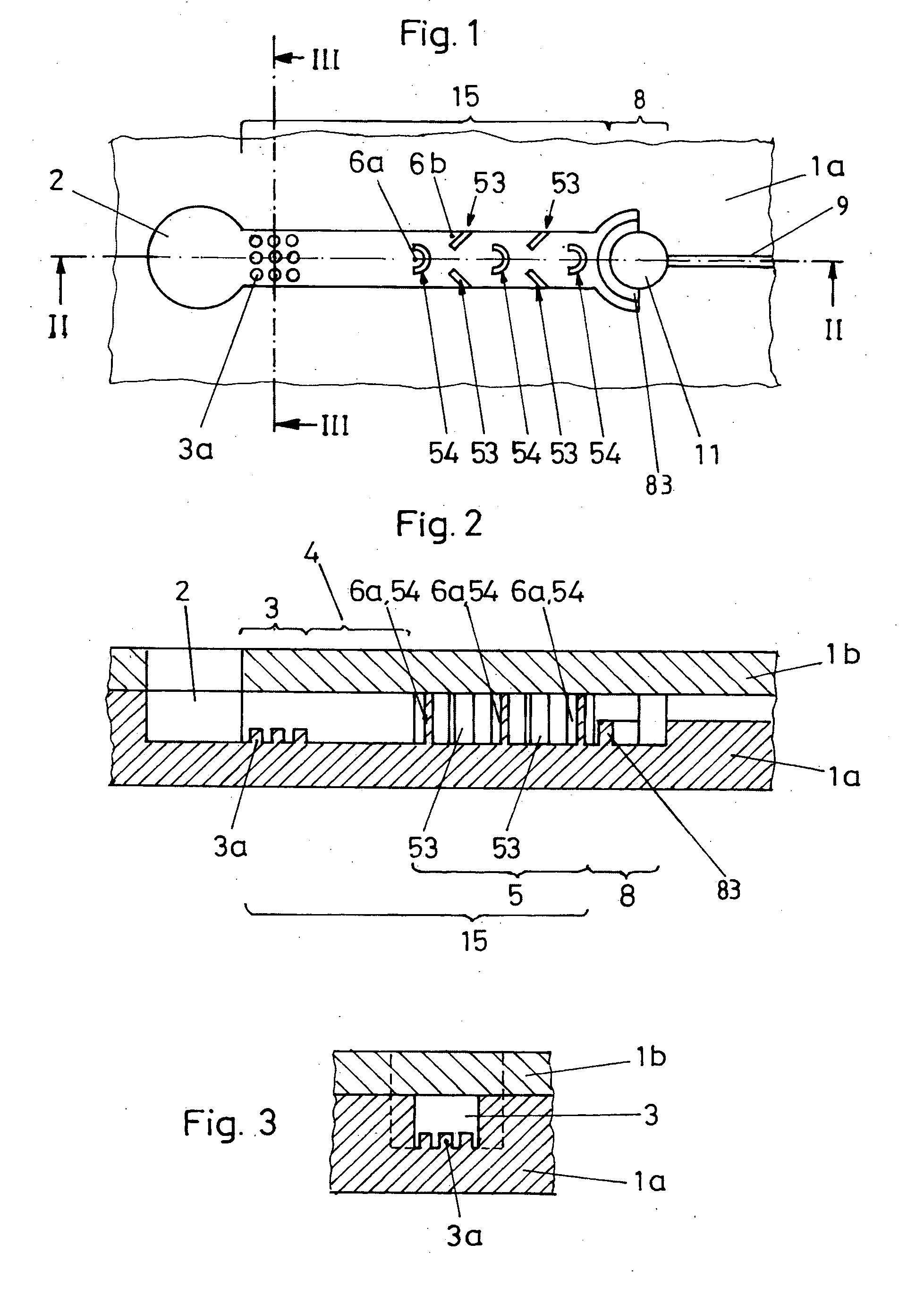
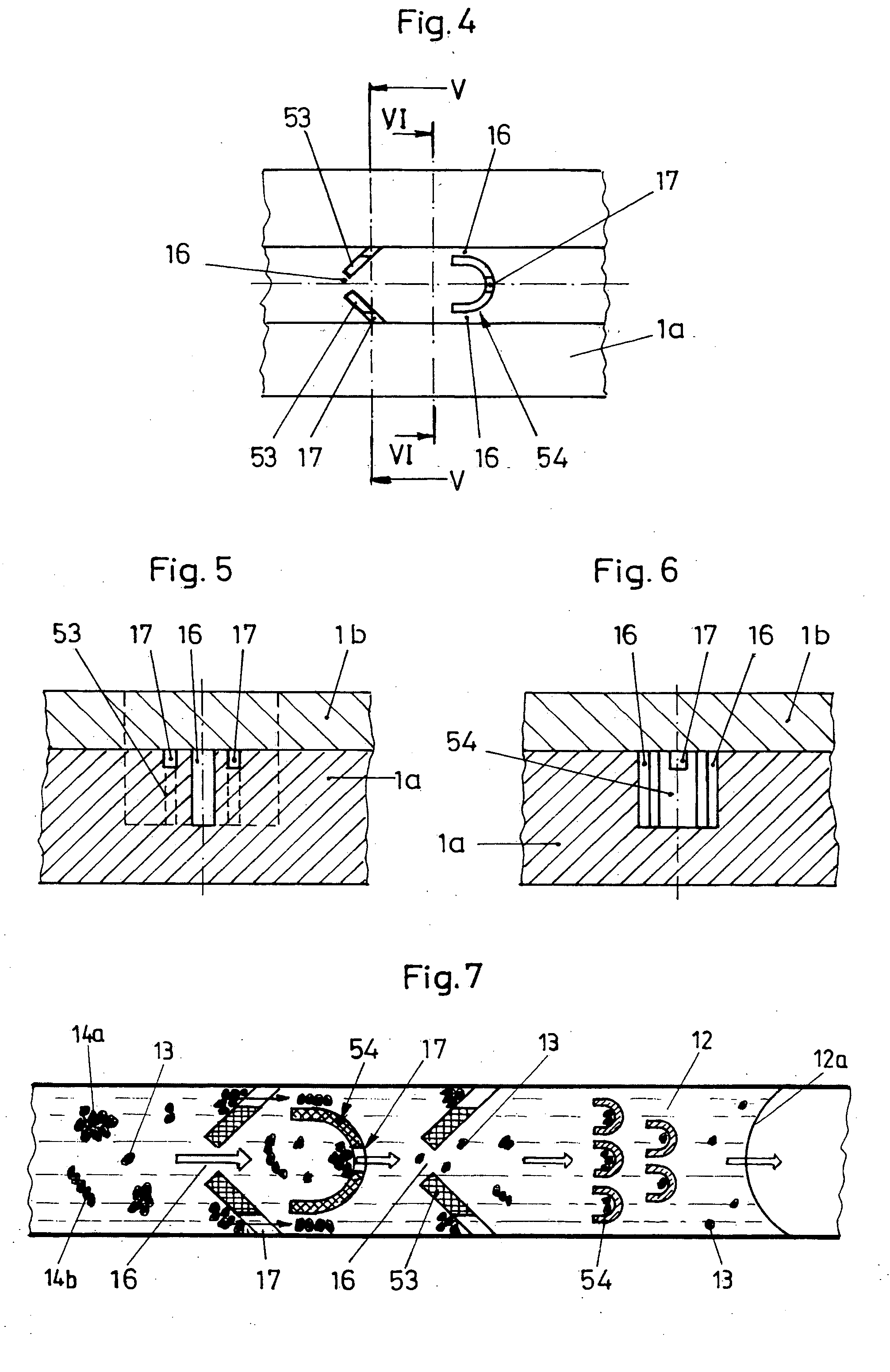
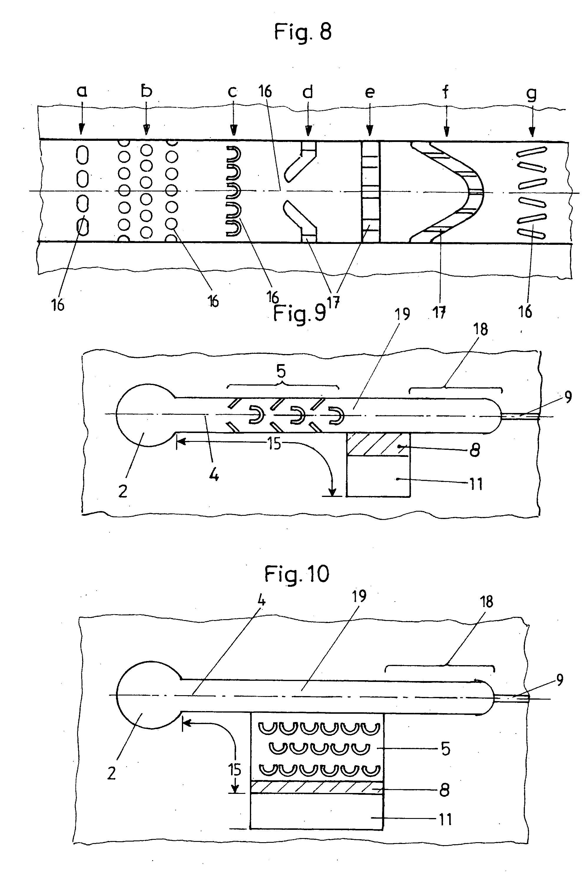
[0060] The illustrative embodiments shown in the figures for separation devices according to the invention show in some cases identical features and in some cases corresponding features, which are labeled with the same reference numbers.

[0061] The first illustrative embodiment shown in FIGS. 1 to 3 has a lower part 1a in which an inlet 2 of circular cross section is formed. From this inlet 2, a first transport path 15 branches off laterally and extends as far as a collection section 11. The collection section 11 is connected to the environment via a vent channel 9. A capillary plug in the transport channel 9 can prevent escape of the liquid components collected in the collection section 11.

[0062] Such a capillary plug can be realized by means of abruptly changing geometric dimensions of the transport channel 9. Likewise, surface properties of the transport channel 9 can abruptly change, for example from hydrophilic to hydrophobic surfaces.

[0063] The transport path 15 between the ...


PUM

PropertyMeasurementUnit
Diameteraaaaaaaaaa
Diameteraaaaaaaaaa
Widthaaaaaaaaaa

Abstract

A microstructured separation device for separating parts of a liquid which comprises liquid components and at least one type of particle and / or at least one complex of interconnected particles of at least one type, with the following features: the device has an inlet for the liquid, a collection section, and a transport path from the inlet to the collection section; the transport path includes, situated one after the other in the direction of transport, a resuspension section, an incubation section, a first separation section for holding back at least some of the complexes and / or for slowing down the movement of at least some of the complexes and / or at least some of the particles, and a second separation section for holding back at least some of the complexes and / or at least some of the particles and / or for slowing down the movement of the particles; and the first separation section and second separation section have a microstructure with one or more microstructure elements.

Description

BACKGROUND OF THE INVENTION [0001] The present invention relates to a microstructured separation device for separating parts of a liquid which comprises liquid components and at least one type of particle and / or at least one complex of interconnected particles of at least one type. [0002] Most biochemical tests are performed on cell-free blood fluids, blood plasma or blood serum, because the blood cells or their contents can distort the measurement results. In hematology, filtration and centrifugation techniques have hitherto mainly been employed for this separation. Complete separation of blood cells without destroying their membranes, and without releasing their content into the test solution, is achieved for example by means of a 15-minute centrifugation at 1500 revolutions per minute. Such a method is complex and time-consuming, for which reason alternative solutions have been sought. Moreover, the current procedures described here do not permit handling of small volumes in the ...

Claims


Application Information

Patent Timeline
IPC IPC(8): G01N33/48B01F5/06B01F13/00B01L3/00G01N1/28G01N33/483G01N33/49
CPCB01F13/0059B01F2005/0621B01F2005/0625B01L3/502753B01L2200/0668G01N1/4077B01L2300/0681B01L2300/18B01L2400/0406B01L2400/086B01L2200/10B01F25/4317B01F25/4316B01F33/30
Inventor BLANKENSTEIN, GERTMARQUORDT, CLAUS
Owner BOEHRINGER INGELHEIM MICROPARTS
Learn More