Automated mechanical transmission system

a transmission system and automatic technology, applied in the direction of gearing control, gearing element, belt/chain/gearing, etc., can solve the problems of reducing the longevity of the absolute torque, relatively complicated sensing of absolute torque,

Inactive Publication Date: 2005-05-26
ZF MERITOR L L C
View PDF66 Cites 55 Cited by
  • Summary
  • Abstract
  • Description
  • Claims
  • Application Information

AI Technical Summary

Problems solved by technology

Disadvantageously, sensing of the absolute torque may be relatively complicated and subject the sensing members to significant stress which may thereby reduce their longevity.

Method used


Image

  • Automated mechanical transmission system
  • Automated mechanical transmission system
  • Automated mechanical transmission system

Examples


Embodiment Construction

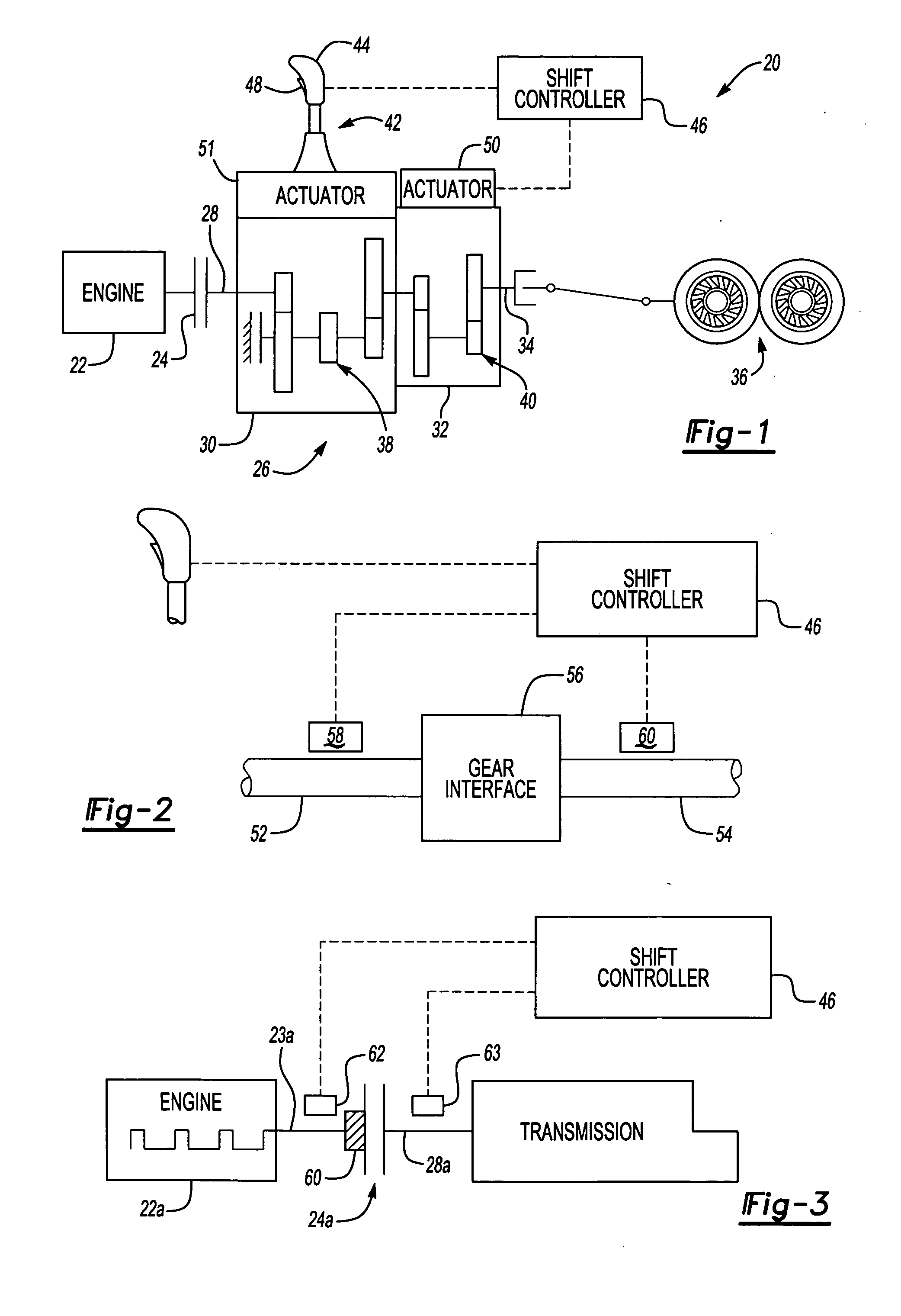
[0018]FIG. 1 diagrammatically illustrates a vehicle driveline 20 incorporating an engine 22 driving a clutch mechanism 24. The clutch mechanism 24 is selectively engaged to transmit power from the engine 22 into an automated mechanical transmission system 26. The clutch 24 can be a “dry clutch” or a “wet clutch”, a centrifugal clutch, releaser clutch, or any other known clutch mechanism.

[0019] The transmission 26 includes an input shaft 28 that is rotationally driven by the engine 22, a main section 30, an auxiliary section 32, and an output shaft 34 that rotatably drives one or more wheels 36 of the vehicle. As is well known, the main section 30 provides a first plurality of gears ratios 38, while the auxiliary section 32 provides a second plurality of gear ratios 40.

[0020] The transmission is shown schematically, and such automated transmissions are known in the art. Although this invention will be described in the context of a range type auxiliary section, it will be appreciate...


PUM


Abstract

A transmission system which relates the relative movement of vehicle components to determine the onset of zero relative torque to permit a shift change to be effected at approximately zero relative torque. When a predetermined signature is identified which relates to the onset of zero relative torque the transmission shift controller initiates a shift.

Description

BACKGROUND OF THE INVENTION [0001] The present invention relates to an automated mechanical transmission systems, and more particularly to an automated transmission system that identifies relative torques present within the power path to permit change of gear ratios. [0002] Heavy vehicles have typically been provided with a manual or automatic clutch and an automatic, automated, or manual transmission. Automated transmission systems that change gear ratios without the assistance of a controllable master clutch must address the problem of how to disengage gears while under torque load. The torque load produces excess force at the gear interface and the resulting friction prevents movement within the limits of available control force. It is desirable, if not mandatory, that the load be relieved prior to disengagement. [0003] The zero torque value at the gear interface changes dynamically with such factors as road conditions, vehicle condition, vehicle configuration, vehicle accelerati...

Claims


Application Information

Patent Timeline
Patent Type & Authority Applications(United States)
IPC IPC(8): F16H59/46F16H61/04
CPCF16H59/46F16H61/0437Y10T74/1926F16H2059/462F16H2059/147
Inventor DEVORE, JAMES HENRYSAYMAN, ROBERT ANTHONYALLEN, CHARLES E. JR.STURMER, WINFRIEDHEINZELMANN, KARL-FRITZRONGE, LUDGERDREIER, LOREN CHRISTOPHERMUETZEL, RONALD PETERABUSAMRA, MUNEER
Owner ZF MERITOR L L C
Why Eureka
Try Eureka