

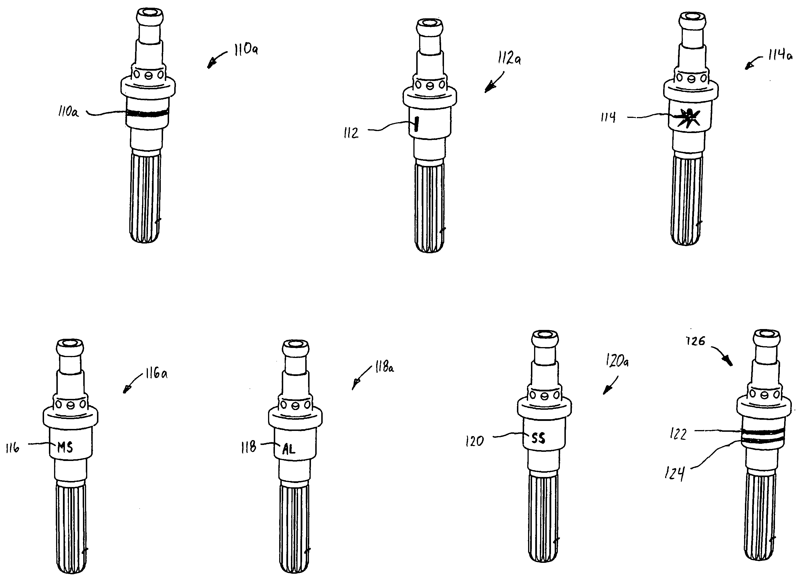
Color coding of plasma arc torch parts and part sets
a technology color code, which is applied in the field of color code of plasma arc torch parts and part sets, can solve the problems of additional deleterious heating, shield cup distortion, and high consumption of tip and electrode in particular
- Summary
- Abstract
- Description
- Claims
- Application Information
AI Technical Summary
Problems solved by technology
Method used
Image

Examples
Embodiment Construction
[0029] The following description of the preferred embodiments is merely exemplary in nature and is in no way intended to limit the invention, its application, or uses.
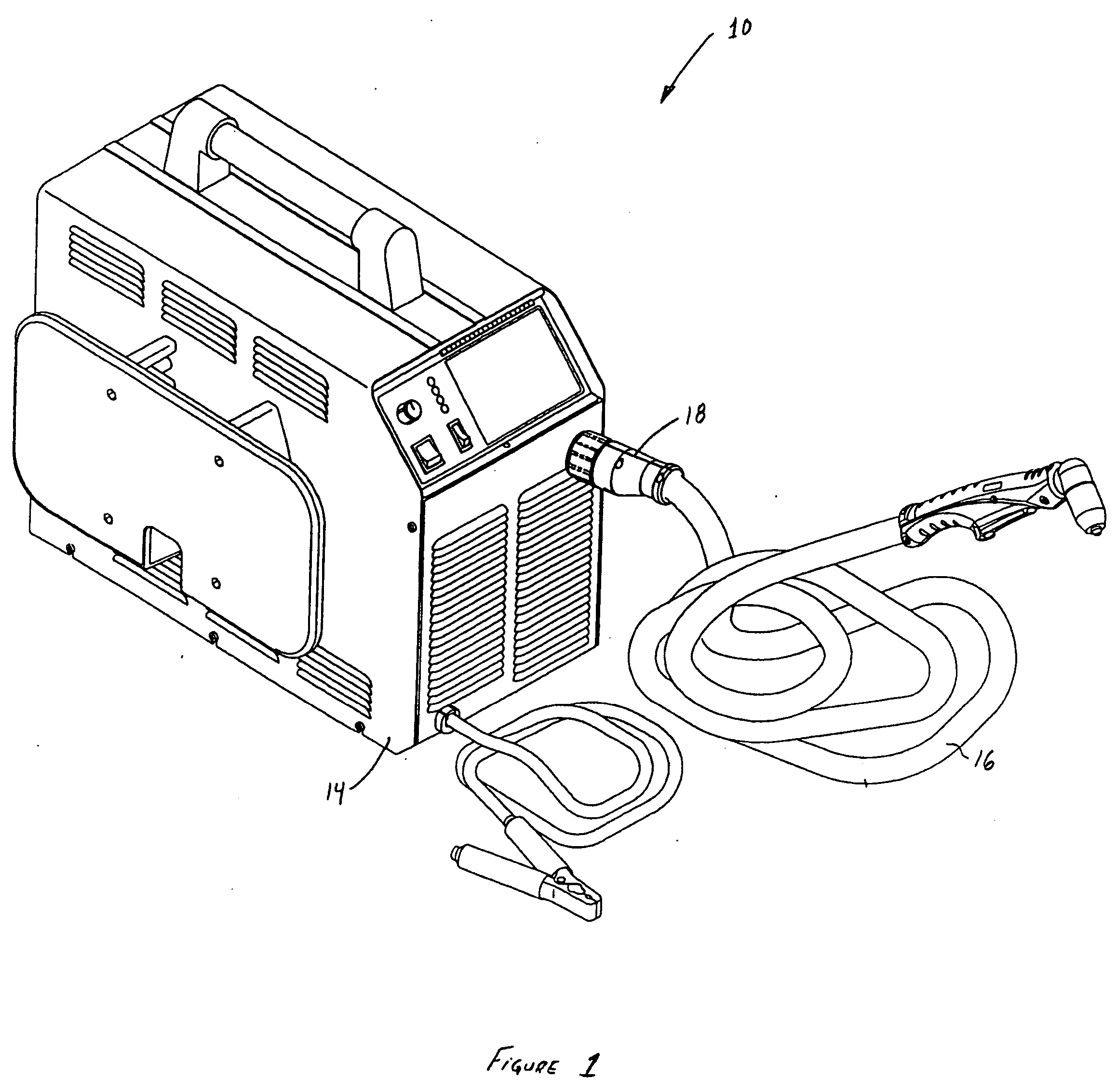
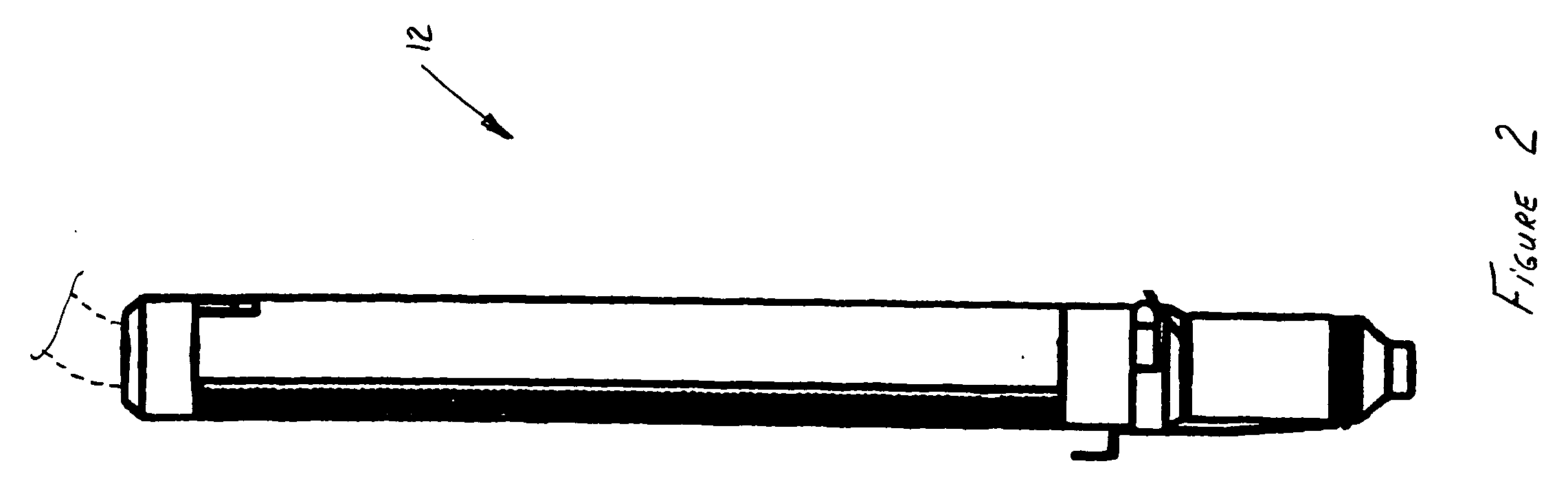
[0030] Referring to the drawings, color coded replacement parts according to the present invention are generally operable with either a manual plasma arc torch 10 or an automated plasma arc torch 12 as indicated in FIGS. 1 and 2, respectively. Generally, the manual plasma arc torch 10 is connected to a power supply 14 through a torch lead 16, which may be available in a variety of lengths according to a specific application. As further shown, the torch lead 16 is connected to the power supply 14 using a quick disconnect 18, although other adapters and connectors may also be used while remaining within the scope of the present invention. In operation, the power supply 14 provides both gas and electric power, which flow through the torch lead 16, to the plasma arc torch 10. The automated plasma arc torch 12 operates sim...
PUM
| Property | Measurement | Unit |
|---|---|---|
| diameters | aaaaa | aaaaa |
| diameters | aaaaa | aaaaa |
| diameters | aaaaa | aaaaa |
Abstract
Description
Claims
Application Information