Welding method
a welding method and welding method technology, applied in the direction of electron beam welding apparatus, crystal growth process, machine/engine, etc., can solve the problems of cracks or fractures in these directions, casting defects during a manufacturing process, and the strength of the repaired part is problematically reduced
- Summary
- Abstract
- Description
- Claims
- Application Information
AI Technical Summary
Benefits of technology
Problems solved by technology
Method used
Image

Examples
first embodiment
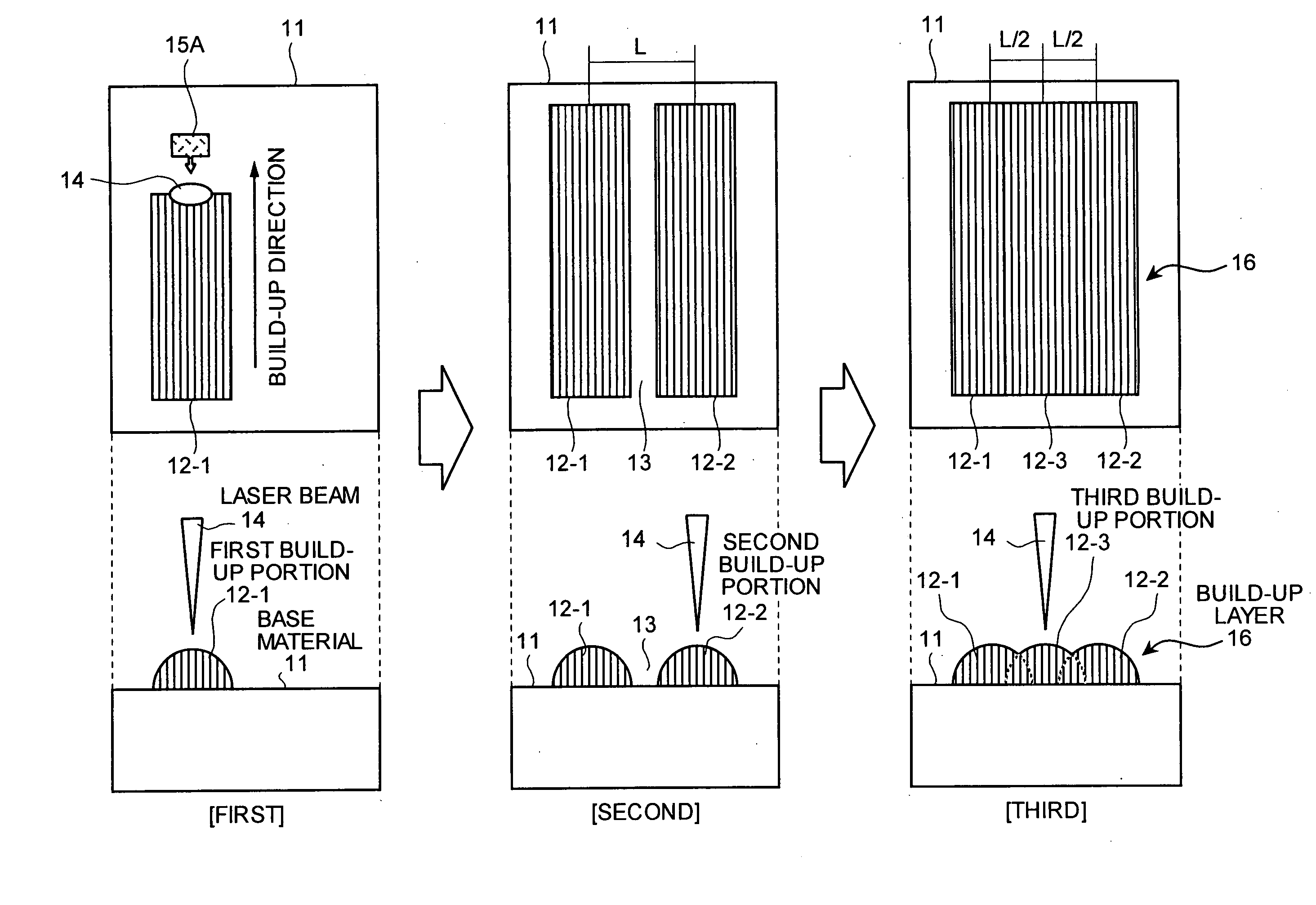
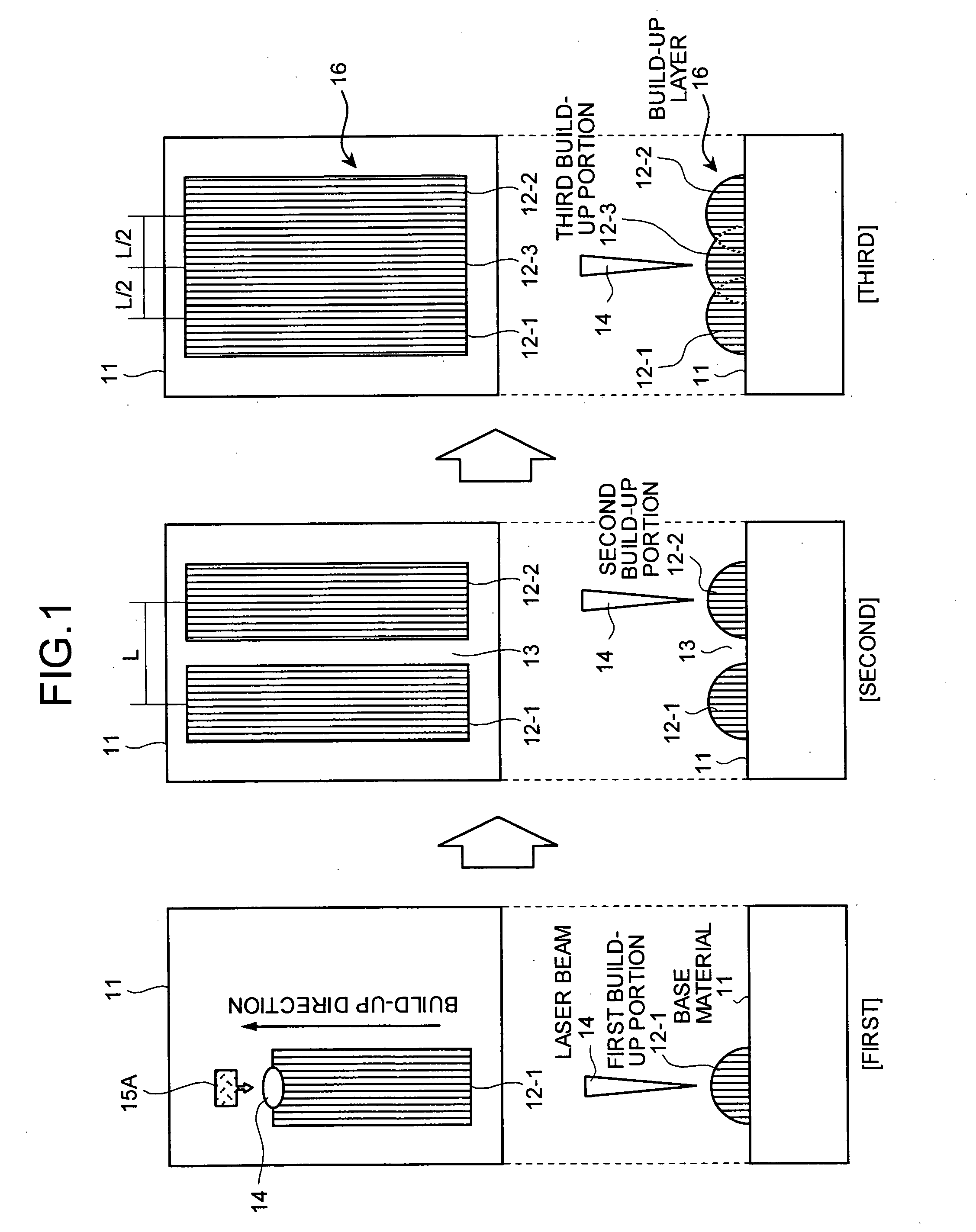
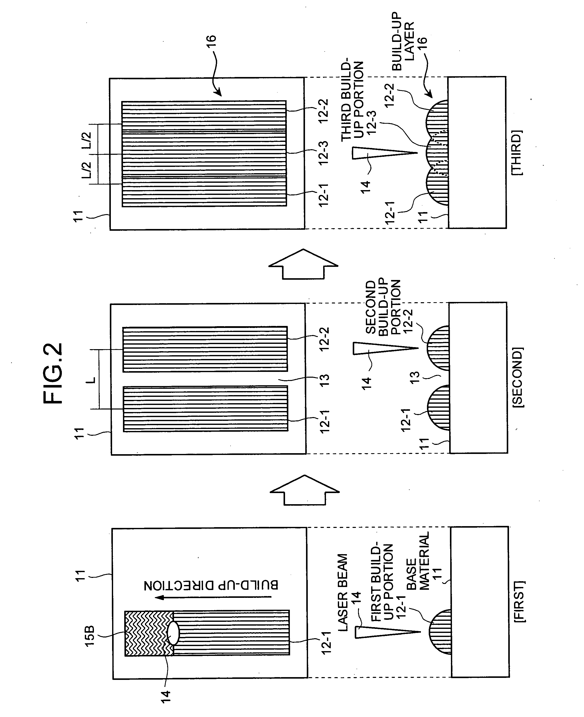
[0040]FIG. 1 is a process diagram for explaining formation of a build-up layer according to the The upper part of FIG. 1 is a top view, and the lower part is a side view.
[0041] A method according to the first embodiment of the present invention includes forming a molten build-up portion 12 on a base material of single crystal or unidirectionally solidified crystal through heating by a heat source. A plurality of build-up portions (two build-up portions in the present embodiment), a first build-up portion 12-1 and then a second build-up portion 12-2 are formed having a predetermined gap 13 between the first and second build-up portions, then a third build-up portion 12-3 is formed in the gap 13.
[0042] It is possible to soundly form a single crystal, because the third build-up portion 12-3 is formed in the gap between the first build-up portion 12-1 and the second build-up portion 12-2.
[0043] Namely, it is possible to form the second build-up portion 12-2 without a thermal influenc...
second embodiment
[0051] A method of forming a build-up portion according to the present invention is a welding method of forming a molten build-up portion 12 on a base material of single crystal or unidirectionally solidified crystal through heating by a heat source. A plurality of build-up portions (five build-up portions in the present embodiment), a first build-up portion 12-1, a second build-up portion 12-2, a third build-up portion 12-3, a fourth build-up portion 12-4, and a fifth build-up portion 12-5 are formed having a predetermined gap 13. From a sixth build-up portion 12-6 to a ninth build-up portion 12-9 are formed in gaps 13-1 to 13-4 forming a first build-up layer 16-1.
[0052] Next, a tenth build-up portion 12-10, an eleventh build-up portion 12-11, a twelfth build-up portion 12-12, a thirteenth build-up portion 12-13, and a fourteenth build-up portion 12-14 are formed on the first build-up layer 16-1 having gaps 13-5 to 13-8. From a fifteenth build-up portion 12-15 to an eighteenth buil...
third embodiment
[0059] The method of building-up according to the present invention, when the base material 11 has a defective portion 21, the defective portion 21 is removed, then a build-up portion is formed in the portion where the defective portion 21 is removed to repair the defective portion.
[0060] As shown in FIG. 6, the defective portion 21 is removed from the base material 11 to form a concave portion 22. Opposite surfaces of an edge preparation portion of the concave portion 22 are beveled forming a first beveled portion 23-1 and a second beveled portion 23-2.
[0061] Then, using the same method as the method of the first embodiment, a plurality of build-up portions (three build-up portions in the present embodiment), the first build-up portion 12-1, the second build-up portion 12-2, the third build-up portion 12-3 are formed having a predetermined gap 13. From the fourth build-up portion 12-4 to the seventh build-up portion 12-7 are formed respectively in the gaps 13-1, 13-2, 13-3 that is...
PUM
| Property | Measurement | Unit |
|---|---|---|
| solidus temperature | aaaaa | aaaaa |
| grain size | aaaaa | aaaaa |
| temperature | aaaaa | aaaaa |
Abstract
Description
Claims
Application Information
 - R&D
- Intellectual Property
- Life Sciences
- Materials
- Tech Scout
- Unparalleled Data Quality
- Higher Quality Content
- 60% Fewer Hallucinations
Browse by: Latest US Patents, China's latest patents, Technical Efficacy Thesaurus, Application Domain, Technology Topic, Popular Technical Reports.
© 2025 PatSnap. All rights reserved.Legal|Privacy policy|Modern Slavery Act Transparency Statement|Sitemap|About US| Contact US: help@patsnap.com