Variable delay circuit
a delay circuit and variable delay technology, applied in pulse manipulation, pulse technique, instruments, etc., can solve the problems of delay precision deterioration and comply with
- Summary
- Abstract
- Description
- Claims
- Application Information
AI Technical Summary
Benefits of technology
Problems solved by technology
Method used
Image
Examples
Embodiment Construction
[0036] The invention will now be described based on the preferred embodiments, which do not intend to limit the scope of the present invention, but exemplify the invention. All of the features and the combinations thereof described in the embodiment are not necessarily essential to the invention.
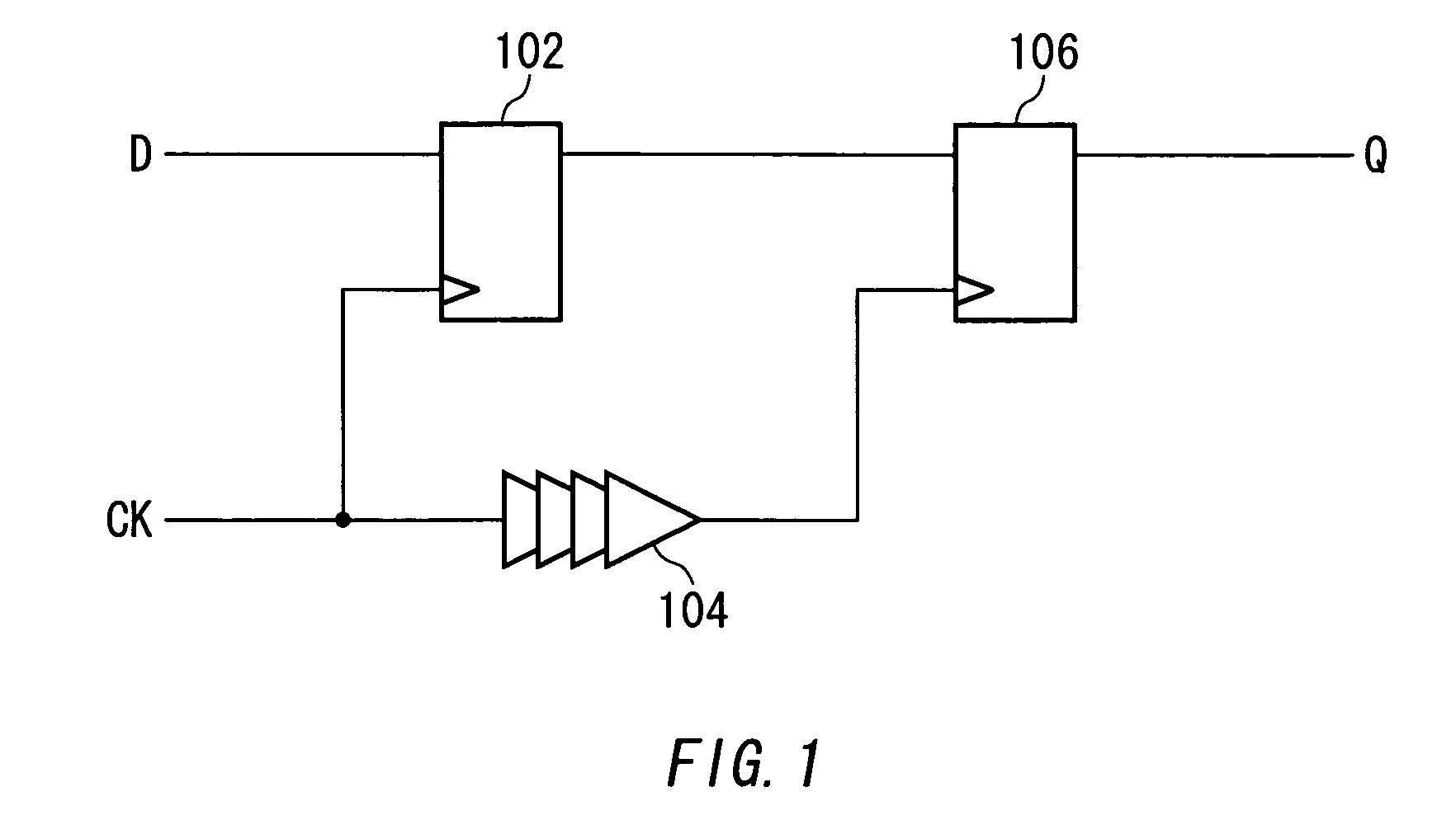
[0037]FIG. 1 shows an example of the configuration of a timing comparator 100 according to the present invention. The timing comparator 100 includes a dynamic D flip-flop circuit 102, a buffer 104 and a positive feed-back D flip-flop circuit 106, and samples and outputs a data signal (D) by a clock signal (CK). The dynamic D flip-flop circuit 102 latches and outputs the data signal (D) with its parasitic capacitance based on the clock signal (CK) received by the timing comparator 100 and supplies it to the positive feed-back D flip-flop circuit 106. The buffer 104 delays the clock signal (CK) received by the timing comparator 100 by a predetermined time and supplies it to the positive feed-...
PUM
 Abstract
Description
Claims
Application Information
 - R&D
- Intellectual Property
- Life Sciences
- Materials
- Tech Scout
- Unparalleled Data Quality
- Higher Quality Content
- 60% Fewer Hallucinations
Browse by: Latest US Patents, China's latest patents, Technical Efficacy Thesaurus, Application Domain, Technology Topic, Popular Technical Reports.
© 2025 PatSnap. All rights reserved.Legal|Privacy policy|Modern Slavery Act Transparency Statement|Sitemap|About US| Contact US: help@patsnap.com


