Method and device for optical sensor compensation, and apparatus incorporating the same

Inactive Publication Date: 2005-05-26
FUJIFILM BUSINESS INNOVATION CORP
View PDF10 Cites 7 Cited by
  • Summary
  • Abstract
  • Description
  • Claims
  • Application Information

AI Technical Summary

Benefits of technology

[0013] In order to lower cost and improve the life and performance of a printing or copying apparatus, a self compensating optical sensor device, method, and apparatus is desirable that compensates for degradation due to contamination, such as from dust, fluid misting or splashing. This extend

Problems solved by technology

A recurring problem in ink jet printing or xerographic copying is the contamination of optical sensors, particularly those in the paper path.
Particularly, during the life of the ink jet printer, these airborne particles together may become c

Method used


Image

  • Method and device for optical sensor compensation, and apparatus incorporating the same
  • Method and device for optical sensor compensation, and apparatus incorporating the same
  • Method and device for optical sensor compensation, and apparatus incorporating the same

Examples


Embodiment Construction

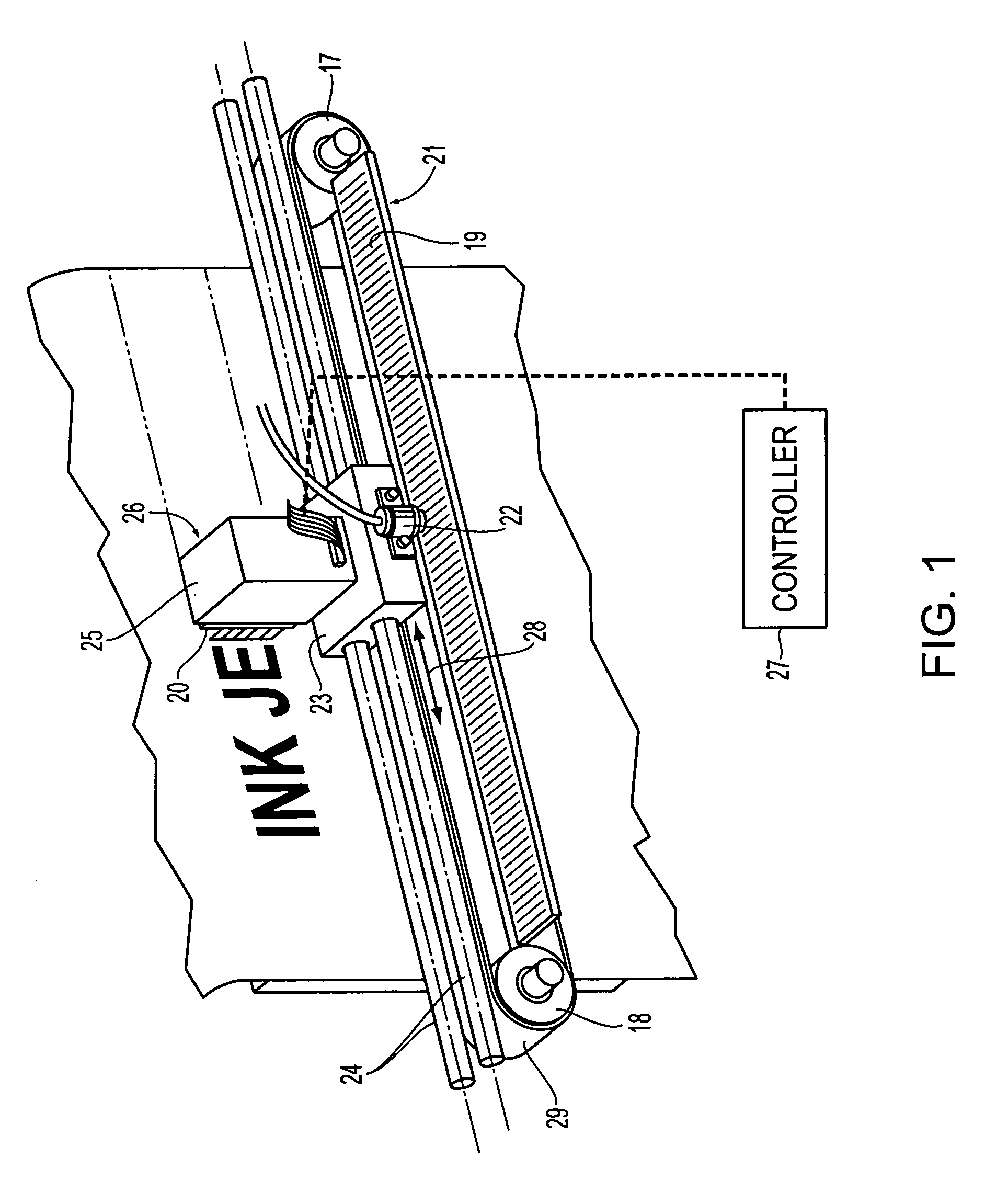
[0034] The following detailed description of various exemplary embodiments of an optical sensor method, device for optical sensor compensation due to contamination, and an apparatus incorporating the same may be usable with various devices incorporating one or more optical sensors in an environment subjected to contamination over time. In exemplary embodiments, this may be within fluid ejection systems or other technologies that store and consume fluids. One specific type of fluid ejection system, e.g., an inkjet printer, forms an exemplary method and device according to this invention, for sake of clarity and familiarity. However, it should be appreciated that the principles of this invention, as outlined and / or discussed below, can be equally applied to any known or later-developed fluid ejection systems, for example a xerographic reproduction apparatus, beyond the ink jet printer specifically discussed herein.

[0035] Several exemplary methods and devices for optical sensor compen...


PUM


Abstract

An optical sensor has a sensor compensation to compensate for sensor degradation due to airborne contaminations in the operating environment. For example, in a thermal ink jet printing environment, the thermal ink jet operation produces misting or splashing of the thermal ink jet droplets, causing a gradual degradation of the sensor sensitivity due to a surface accumulation of the ink jet droplets. The optical sensor device includes an optical emitter emitting an optical signal according to an emitter input, an optical detector disposed to detect the optical signal and output a detector output having an output level according to the detected optical signal, a variable attenuator having an adjustable attenuation setting, and a controller adjusting the attenuation setting of the variable attenuator. During an adjustment operation, the controller determines the attenuation setting at which the output level of the detector output exceeds a predetermined value, and accordingly sets the variable attenuator to operate the detector output at an output level exceeding the predetermined value by a margin. Compensations for the optical emitter and the optical detector are disclosed, including the use of a variable pulse-width modulated signal.

Description

BACKGROUND OF THE INVENTION [0001] 1. Field of Invention [0002] This invention relates generally to a method and device for optical sensor compensation to automatically adjust for sensor degradation, and an apparatus incorporating the same. [0003] 2. Description of Related Art [0004] Fluid ejector systems, such as drop-on-demand liquid ink printers, have at least one fluid ejector from which droplets of fluid are ejected towards a receiving sheet. Scanning inkjet printers are equipped with fluid ejection heads containing fluid ink. The ink is applied to a sheet in an arrangement based on print data received from a computer, scanner or similar device. To control the delivery of the fluid to the sheet, fluid ejection heads are moved across the sheet to provide the fluid to the sheet, which is ejected as drops. These drops correspond to a liquid volume designated as pixels. Each pixel is related to a quantity needed to darken or cover a particular unit area. [0005] An exemplary fluid e...

Claims


Application Information

Patent Timeline
IPC IPC(8): B41J2/125B41J2/01B41J11/42B41J19/18G01J1/26G03G21/00
CPCG01J1/26B41J2/125
Inventor MERZ, ERIC A.FUJIMURA, YOSHIHIKO
Owner FUJIFILM BUSINESS INNOVATION CORP
Why Eureka
Try Eureka