Handheld electronic device

a technology of electronic devices and hand-held devices, which is applied in the direction of electric apparatus casings/cabinets/drawers, pulse techniques, instruments, etc., can solve the problems of inconvenient text message input by users to mobile phones, keyboard b, /b> cannot be provided with a large number of keys, etc., and achieve the effect of quick input into the devi

Inactive Publication Date: 2005-05-26
HTC CORP
View PDF14 Cites 30 Cited by
  • Summary
  • Abstract
  • Description
  • Claims
  • Application Information

AI Technical Summary

Benefits of technology

[0011] An object of the present invention is to provide a handheld electronic device having a pivotal structure pivotably connecting a sliding member and a body of the handheld electronic device together wherein the sliding member is provided with a keyboard thereon. The pivotal structure is so located that after the sliding member is rotated related to the body, the sliding member extends across a part of the body to cause the device to have an inverted “T” configuration, whereby a user of the device can easily use his (her) two thumbs to type the keyboard so that a text message can be quickly entered into the device.

Problems solved by technology

However, since a handheld device only has a palm size, wherein a display of the device occupies most of the area, area available for a keyboard thereof is small; the keyboard thus cannot be provided with a large number of keys, which is disadvantageous when a user needs to input text message into the handheld device.
Such a keyboard 14 is inconvenient for a user to input text messages to the mobile phone 10.
Yet the large external keyboard 16 occupies too much space, which is not valid for portable purpose.
Furthermore, to simultaneously carry the mobile phone 10 and the external keyboard 16 is not convenient.
Furthermore, the increase of width brings inconvenience for the user to hold the device 20 by his (her) palm.
Therefore, ergonomics is not complied with the operation, and slow data input with single hand is caused.
In addition, since the keyboards are entirely located at a lateral side of the bodies of the devices, it is not convenient for the user to watch the displays while keying the text messages to check out the correctness of his (her) typing.

Method used


Image

  • Handheld electronic device
  • Handheld electronic device
  • Handheld electronic device

Examples


first preferred embodiment

[0035] Referring to FIGS. 5A˜6B, a handheld electronic device in accordance with a first embodiment of the present invention is shown.

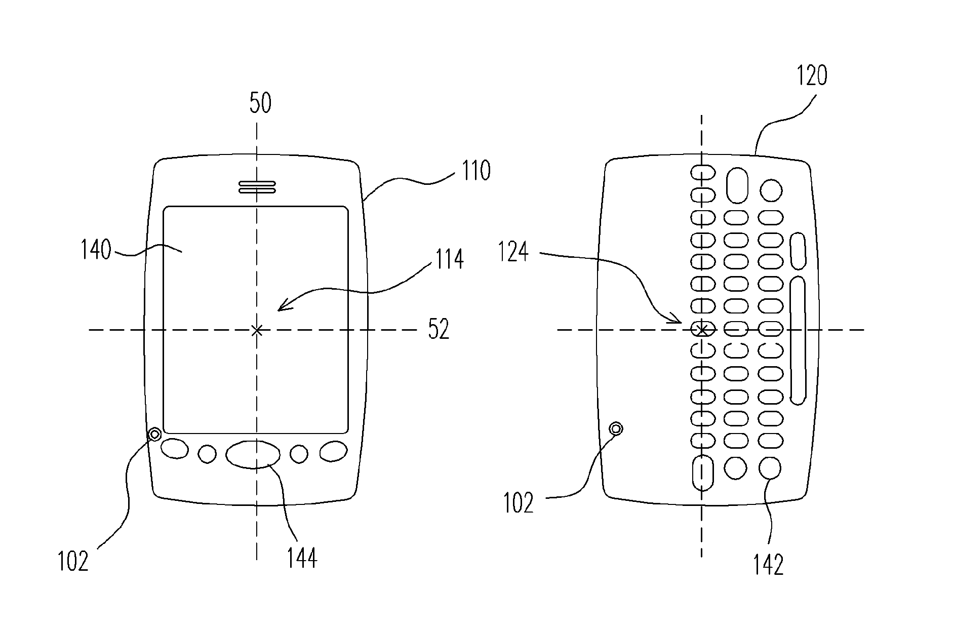
[0036] Please refer to FIG. 5A and FIG. 6A firstly. A pivotal structure 100 is disposed between a body 110 and a sliding member 120, a bottom surface 112 of the body 110 is against a top surface 122 of the sliding member 120, and the sliding member 120 is pivotally connected to the body 110 through the pivotal structure 100. In this preferred embodiment, the body 110 and the sliding member 120 are similar in size, curvature, corner radian, and thickness, so that the body 110 and the sliding member 120 are consistent in profile, whereas the profile is categorized into elongated shape. However other shapes of the body 110 or the sliding member 120 are within the scope of this present invention, for example, regular polygon (equivalent triangle, equivalent tetragon, equivalent pentagon, etc.), or circle and ellipse, also fall within the scope of the pre...


PUM


Abstract

A handheld electronic device has a body (110) and a sliding member (120) wherein the body is pivotably mounted on the sliding member by a pivot axle (102). The body is provided with a display (510) thereon, and the sliding member is provided a keyboard (520) thereon. When the sliding member is lengthwise aligned with the body, the keyboard is hidden below the body. When the sliding member is rotated relative to the body to reach a position wherein the sliding member is at an orientation perpendicular to that of the body, the keyboard is exposed and has two end portions located outside of lateral sides of the body, respectively.

Description

CROSS REFERENCE TO RELATED APPLICATIONS [0001] This application claims the priority benefit of Taiwan application serial no. 92219504, filed Nov. 3, 2003. BACKGROUND OF INVENTION [0002] 1. Field of the Invention [0003] This invention generally relates to a handheld electronic device, and more particularly to a handheld electronic device having a body and a sliding member pivotably connected together, wherein the body is provided with a display and the sliding member is provided with a keyboard. The sliding member is pivotable relative to the body between closed and opened positions. At the closed position, the sliding member is hidden below the body, and at the opened position, the sliding member is exposed and extends across a part of the body. [0004] 2. Description of Related Art [0005] A handheld electronic device is a miniature, portable electronic device, such as a mobile phone, a handheld PC, or a personal digital assistant (PDA). Since a handheld electronic device applies to ...

Claims


Application Information

Patent Timeline
Patent Type & Authority Applications(United States)
IPC IPC(8): G06F1/16G06F3/02H04M1/02H04M1/23
CPCG06F1/1622G06F1/1624H04M1/23H04M1/0227H04M1/0231G06F1/1666
Inventor WANG, JOHN C.
Owner HTC CORP
Why Eureka
Try Eureka