
VLAN server

a virtualareanetwork and server technology, applied in the field of virtualareanetwork servers, can solve the problems of increasing the amount of used hardware, increasing the cost of installing one server in each vlan, increasing the amount of used memory, etc., and achieves the effect of convenient implementation

Inactive Publication Date: 2005-05-26
HITACHI LTD
View PDF27 Cites 169 Cited by
  • Summary
  • Abstract
  • Description
  • Claims
  • Application Information

AI Technical Summary

Benefits of technology

[0025] Conventionally, a usual server connected to a LAN has only one TCP / IP stack. When the server is used as a server shared by VLANs, the TCP / IP stack does not need to be changed, but only drivers need to be changed, according to the present invention. Therefore, a server shared by VLANs can be easily implemented.

Problems solved by technology

When a service usually provided by one server, such as a web application and a file transfer function, is provided for VLANs, it is disadvantageous in terms of cost and in terms of operation and administration to install one server in each VLAN.
In Japanese Unexamined Patent Publication No. 2003-167805, however, since a plurality of TCP / IP stacks and a plurality of device drivers are provided, a memory needs to have the same number of data items of each type, such as a routing table for determining a path to a communication destination and an address-resolution-protocol (ARP) table for managing the correspondence between an IP address and a MAC address, as the number of closed networks, which may cause an increase in the amount of used memory.
In addition, in Japanese Unexamined Patent Publication No. 2003-167805, each of the communication flows for closed networks A to C corresponds to one computer, and therefore, the same number of computers as the number of the closed networks are required, which may cause an increase in used hardware.

Method used


Image

  • VLAN server
  • VLAN server
  • VLAN server

Examples


Embodiment Construction

[0038] A VLAN server for providing services for a plurality of VLANs with the use of only one TCP / IP stack will be described below.

1. Structure of VLAN Server

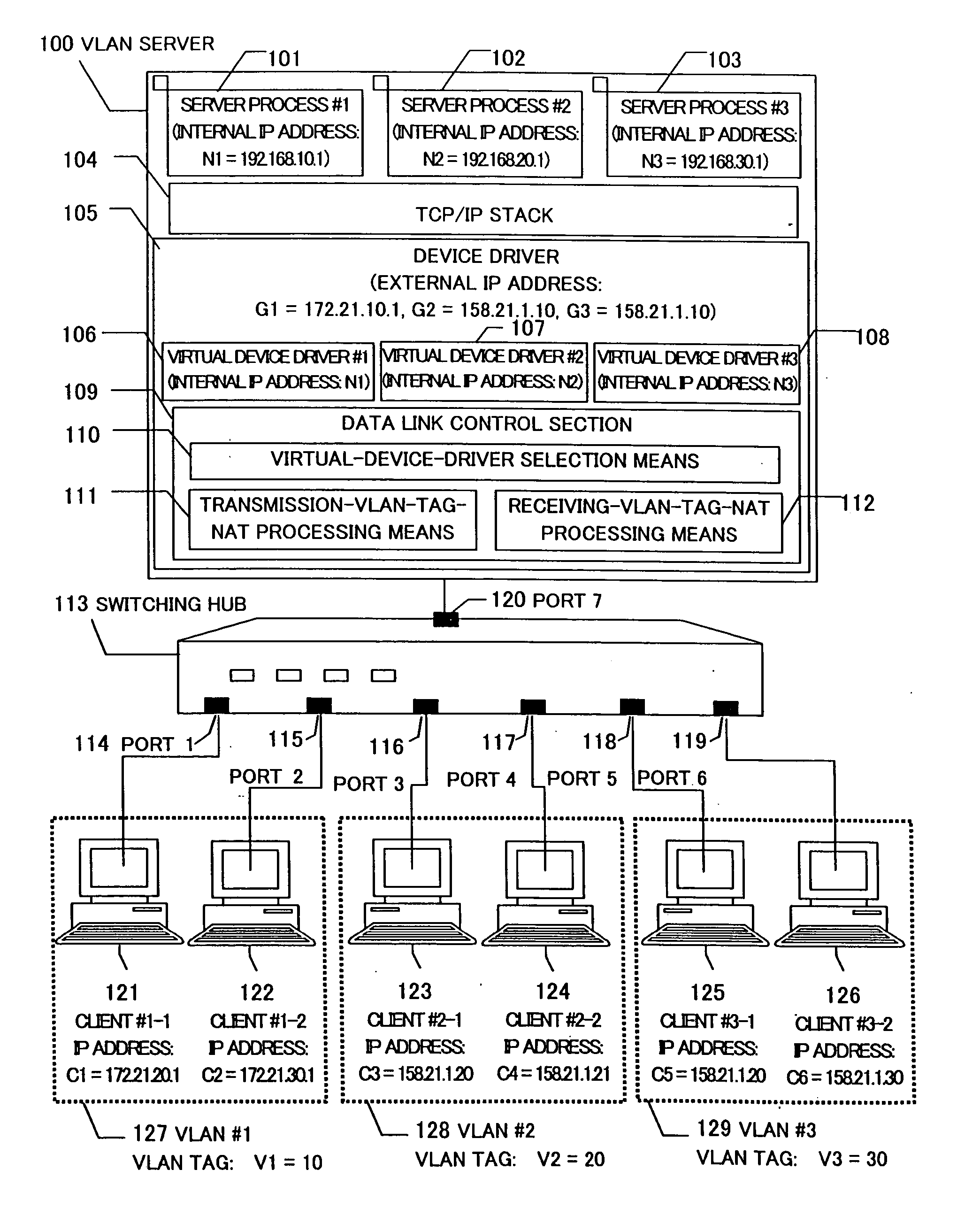
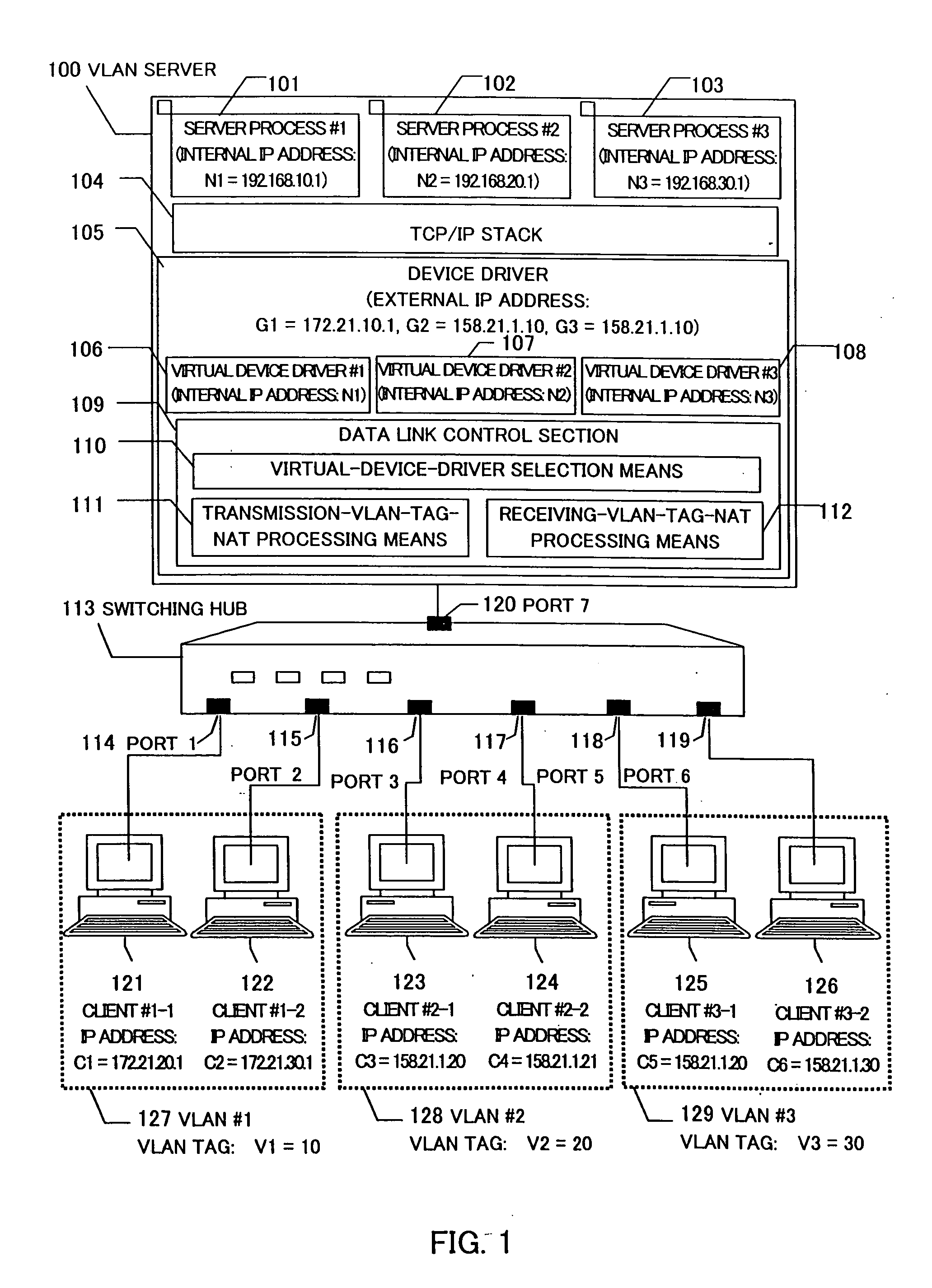
[0039]FIG. 1 is a system configuration view according to an embodiment of the present invention.

[0040] Usually, a VLAN server accommodates a plurality of VLANs. In the present embodiment, the number of VLANs accommodated by a VLAN server 100 is set to three as an example.

[0041] The VLAN server 100 is connected to clients 121 to 126 (clients #1-1 to #3-2) through a switching hub (concentrator) 113. The client 121 (client #1-1) and client 122 (client #1-2) connected to a port 114 (port 1) and a port 115 (port 2) of the switching hub 113 belong to a VLAN 127 (VLAN #1), the client 123 (client #2-1) and client 124 (client #2-2) connected to a port 116 (port 3) and a port 117 (port 4) of the switching hub 113 belong to a VLAN 128 (VLAN #2), and the client 125 (client #3-1) and client 126 (client #3-2) connected to a port 118 (po...


PUM


Abstract

One physical VLAN server provides a plurality of VLANs with services. VLANs #1 to #3 are connected to the VLAN server though a switching hub. The VLAN server includes server processes #1 to #3 corresponding to the VLANs #1 to #3, respectively, for providing the VLANs with services. The server processes #1 to #3 each have internal IP addresses N1, N2, and N3. The VLAN server has external IP addresses G1, G2, and G3 for the VLANs #1 to #3, respectively. When a client #1-1 on the VLAN #1 issues data to the VLAN server with the destination IP address being set to G1, a receiving-VLAN-tag-NAT processing section of a device driver in the VLAN server changes the destination IP address from G1 to N1 with the use of a VLAN tag V1, and the server process #1 receives the data

Description

BACKGROUND OF THE INVENTION [0001] 1. Field of the Invention [0002] The present invention relates to virtual local-area-network (VLAN) servers, and more particularly, to a physical VLAN server connected to a network which employs TCP / IP and capable of providing services for a plurality of VLANs by itself alone. [0003] 2. Description of the Related Art [0004] A virtual local area network (VLAN) refers to a technology for making a virtual group by terminals connected to a LAN irrespective of their physical connections. [0005] A port VLAN refers to a system in which a port number is assigned to each VLAN in advance in a concentrator (hereinafter called a switching hub) installed in a LAN, a virtual group is formed for the port which each VLAN uses, and communications are made. A tag VLAN (according to the IEEE 802.1Q standard) refers to a system in which a tag (a predetermined value) is assigned to each VLAN in advance in a switching hub constituting a network, a virtual group is forme...

Claims


Application Information

Patent Timeline
Patent Type & Authority Applications(United States)
IPC IPC(8): H04L12/00H04L12/28H04L12/46
CPCH04L12/4645
Inventor NOZUE, DAIKIMIYATA, HIROAKIKAMBE, NORIHIROSHIMIZU, SHINSUKE
Owner HITACHI LTD
Features
  • Generate Ideas
  • Intellectual Property
  • Life Sciences
  • Materials
  • Tech Scout
  • Unparalleled Data Quality
  • Higher Quality Content
  • 60% Fewer Hallucinations
Learn More