Circuit and method for measuring delay of high speed signals

a high-speed signal and delay technology, applied in the field of test and measurement of signals and circuits, can solve the problems of affecting the resolution of the measurement circuit, the measurement accuracy of the measurement circuit is limited, and the resolution is typically overwhelmed by the self-jitter of the measurement circui

Active Publication Date: 2005-05-26
SIEMENS PROD LIFECYCLE MANAGEMENT SOFTWARE INC
View PDF5 Cites 26 Cited by
  • Summary
  • Abstract
  • Description
  • Claims
  • Application Information

AI Technical Summary

Benefits of technology

[0012] An objective of the invention is to measure the performance of circuitry for purposes of ...

Problems solved by technology

As these delays and times continue to decrease to the picosecond realm, measuring them is more difficult due to limits of physics, and accuracy is more important because inaccuracy can greatly affect test yield.
The measurement accuracy of these circuits is limited by jitter in the signals being measured or by jitter in the measurement circuitry itself, an...

Method used


Image

  • Circuit and method for measuring delay of high speed signals
  • Circuit and method for measuring delay of high speed signals
  • Circuit and method for measuring delay of high speed signals

Examples


Embodiment Construction

[0044] In the following detailed description, numerous specific details are set forth in order to provide a thorough understanding of the present invention, However, it will be understood by those skilled in the art that the present invention may be practiced without these specific details. In other instances, well known methods, procedures, components and circuits have not been described in detail so as not to obscure aspects of the present invention.

[0045] The present invention is based on Applicant's aforementioned Application No. 10 / 947,189, which is incorporated herein by reference.

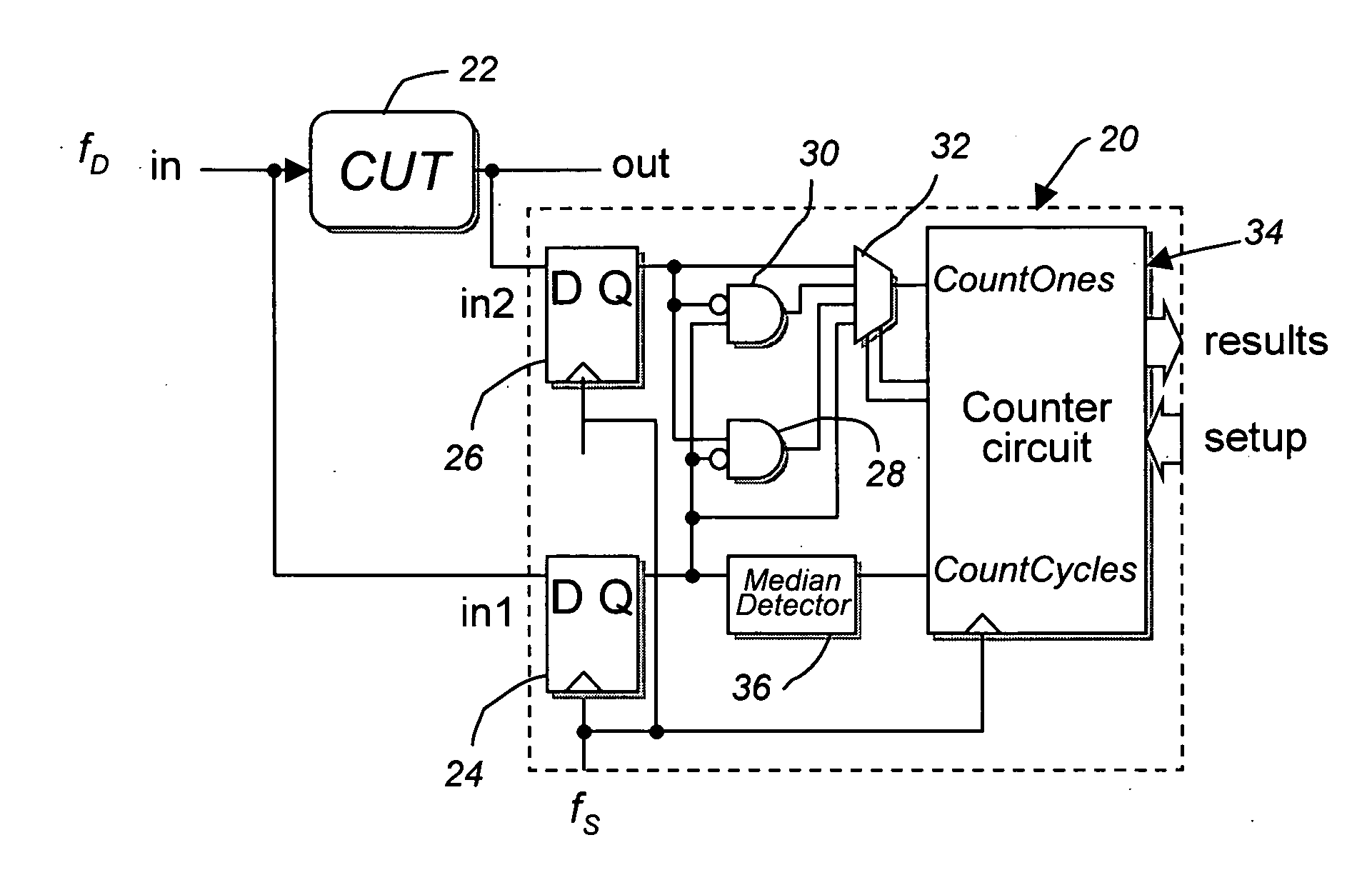
[0046] In the present invention, consistent with the aforementioned application, a periodic input signal, having data that is clocked at a data frequency, fD, is applied to the CUT. The input and the output of the CUT are coherently undersampled by latches clocked at a sampling frequency, fS. The frequencies are chosen so that the ratio of the sampling frequency to the data frequency, i.e., fD / fS, ...


PUM


Abstract

A method and circuit for measuring a time interval between transitions of periodic signals at nodes of a circuit-under-test (CUT), the signals having a periodic clock frequency, the method comprises periodically latching a digital value of a first periodic signal at edges of an undersampling clock, simultaneously periodically latching a digital value of a second periodic signal at edges of the undersampling clock, combining the latched digital values of the first and second periodic signals to produce a combined output whose duty cycle is proportional to the time interval between a median edge of latched digital values of the first periodic signal and a median edge of latched digital values of the second periodic signal; and counting the number of undersampling clock cycles in which the combined output is a predetermined logic value within a predetermined time interval whereat the number is proportional to a time interval between a transition of the first periodic signal and a transition of the second periodic signal.

Description

CROSS-REFERENCE TO RELATED APPLICATIONS [0001] This application claims the benefit of U.S. Provisional Patent Application Ser. No. 60 / 523,323 filed Nov. 20, 2003, 60 / 545,963 filed Feb. 20, 2004 and 60 / 558,102 filed Apr. 2, 2004, all incorporated herein by reference.BACKGROUND OF THE INVENTION [0002] 1. Field of the Invention [0003] The present invention relates to test and measurement of signals and circuits. [0004] 2. Description of Related Art [0005] Propagation delays and transition times of signals in integrated circuits (ICs) are targets of many specifications and tests. As these delays and times continue to decrease to the picosecond realm, measuring them is more difficult due to limits of physics, and accuracy is more important because inaccuracy can greatly affect test yield. [0006] Rise and fall times are typically specified as shown in FIG. 1 at specific voltage thresholds, and for very high speed data signals, the duration relative to the bit duration or unit interval (UI...

Claims


Application Information

Patent Timeline
IPC IPC(8): H04Q1/20
CPCG01R31/31709G01R29/26
Inventor SUNTER, STEPHEN K.ROY, AUBIN P. J.
Owner SIEMENS PROD LIFECYCLE MANAGEMENT SOFTWARE INC
Why Eureka
Try Eureka