Eureka AIR delivers breakthrough ideas for toughest innovation challenges, trusted by R&D personnel around the world.

Method and a system for measuring mail carrying times

a mail carrying time and measurement method technology, applied in the field of measuring quality of service, can solve the problems of increasing implementation costs of measurement systems, and achieve the effect of reducing implementation costs and improving the quality of performance measuremen

Inactive Publication Date: 2015-01-01
SOLYSTIC
View PDF4 Cites 0 Cited by
  • Summary
  • Abstract
  • Description
  • Claims
  • Application Information

AI Technical Summary

Benefits of technology

The invention aims to improve the quality of measuring performance while reducing the cost of implementing it. This is achieved by using real mailerves to measure performance, instead of using dummy mailforms. Each real mailvelope has a unique identifier derived from a digital image, which allows for tracking without affecting its structural integrity. Dummy mail boosts reliability by having machine-readable unique identifiers that can be tracked in contactless manner. The second mail carrying time is measured on a sample of real mailies, thereby rendering the measurement more reliable.

Problems solved by technology

Such measurement systems are becoming increasingly costly to implement, in particular for measuring the times taken for carrying international mail because the number of mail carrying paths over which measurement needs to be performed is increasing due to the number of possible combinations between all of the mail insertion points and all of the mail delivery points.
In addition, for the measurement to be reliable, it is necessary to make the dummy mailpieces indistinguishable from the real mailpieces so that they go imperceptibly past the operators on sorting machines or the like, which is costly.
More particularly, in order to measure quality of service on international mail, it can be necessary to use more than 300,000 test mailpieces per year, while also limiting the measurement to one test mailpiece per day and per mail carrying route.

Method used


Image

  • Method and a system for measuring mail carrying times
  • Method and a system for measuring mail carrying times
  • Method and a system for measuring mail carrying times

Examples


Embodiment Construction

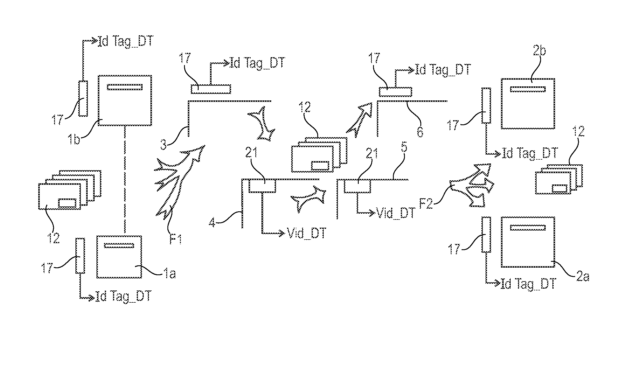
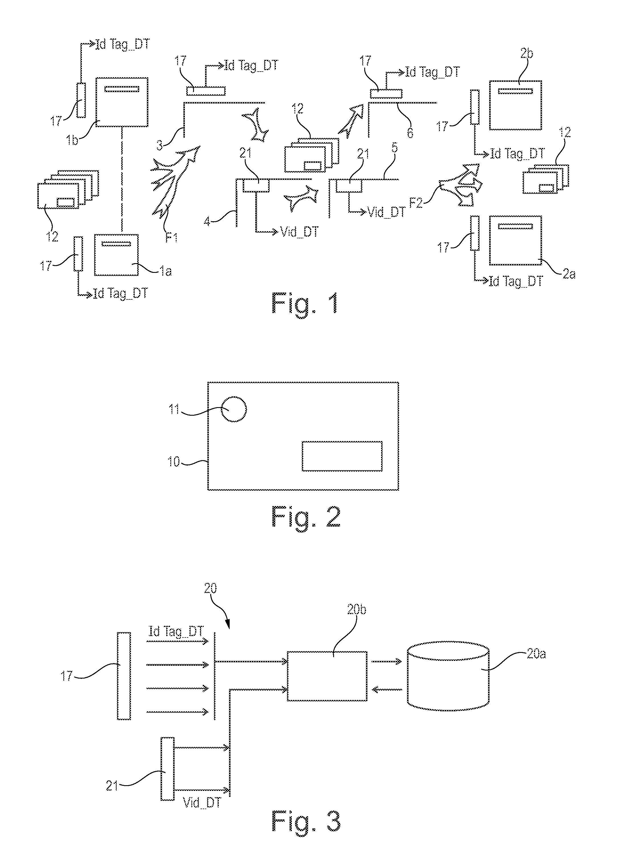
[0033]FIG. 1 is a very diagrammatic view of the architecture of a logistics network that is given by way of example and that serves for inward and outward sorting of international mail, in particular, in this example, with only two national postal authorities.

[0034]In this example, the network comprises first post offices 1a, 1b of a first postal authority, and second post offices 2a, 2b of a second postal authority. For simplification reasons, as regards measuring quality of service for international mail, it is considered that the first post offices 1a, 1b are departure post offices from which the international mail departs and that the second post offices are arrival post offices at which the international mail arrives.

[0035]In a variant, the departure point may be constituted by the sender handing over the test mailpiece to the post office or putting it in a mailbox, and the arrival point may be constituted by the test mailpiece being received by the recipient at the place of re...


PUM


Abstract

A method of measuring the times taken for carrying mail through a network of postal sorting machines between at least a mail departure point and a mail arrival point, which method comprises the following steps, a) using first dummy mailpieces to measure first mail carrying times taken to carry said first dummy mailpieces from the departure point to a certain postal sorting machine of the network; b) using real mailpieces to measure second mail carrying times taken to carry said real mailpieces from said certain sorting machine of the network to another postal sorting machine of the network; and c) using second dummy mailpieces to measure third mail carrying times taken to carry said second dummy mailpieces from said other postal sorting machine to the arrival point.

Description

CROSS-REFERENCE TO RELATED APPLICATIONS[0001]This application claims benefit of French patent application number 1356130, filed Jun. 26, 2013, which is herein incorporated by reference.BACKGROUND OF THE INVENTION[0002]1. Field of the Invention[0003]The invention relates to measuring quality of service between postal authorities, such quality of service being involved in particular in computing financial clearing between such authorities. More particularly, the invention relates to evaluating the logistics performance of the postal authorities, in particular for international mail sent as a “Priority” service, namely evaluating times taken for carrying such mail that goes via postal sorting machines from a departure point situated in one country to an arrival point situated in another country.[0004]2. Description of the Related Art[0005]Conventionally, postal authorities measure the times taken for carrying mail in statistical manner, using dummy mailpieces or test mailpieces that ar...

Claims


Application Information

Patent Timeline
IPC IPC(8): G06Q10/08
CPCG06Q10/083G06Q50/32G06Q10/08G06Q50/60
Inventor BUISSONNET, ERICCAILLON, CHRISTOPHE
Owner SOLYSTIC
Why Eureka
Eureka Blog
Learn More