Method for imaging of pre-stack seismic data

a seismic data and pre-stack technology, applied in the field of geophysical prospecting, can solve the problems of less discussion, inability to achieve numerical application, and inability to achieve the most practical form of application

Inactive Publication Date: 2005-05-26
PGS AMERICA INC
View PDF4 Cites 12 Cited by
  • Summary
  • Abstract
  • Description
  • Claims
  • Application Information

AI Technical Summary

Problems solved by technology

However, there has been considerably less discussion of the dynamic advantages that might (or should) be realized through wave equation-based methods.
Poststack migration is often inadequate for areas that are geologically complex, because the migration is performed at a late stage, after the seismic data have been affected by the NMO (normal moveout) or DMO (dip moveout) corrections and CDP (common depth point) stacking.
Equation (3) provides a representation that is convenient for theoretical analysis, but it is not the most practical form for numerical application.
However, it does not yield a valid measure of reflectivity.
This method can yield “floating point errors” where the source illumination is very weak.
However, it has the undesirable side effect of inhibiting an accurate recovery of geometrical divergence.

Method used


Image

  • Method for imaging of pre-stack seismic data
  • Method for imaging of pre-stack seismic data
  • Method for imaging of pre-stack seismic data

Examples


Embodiment Construction

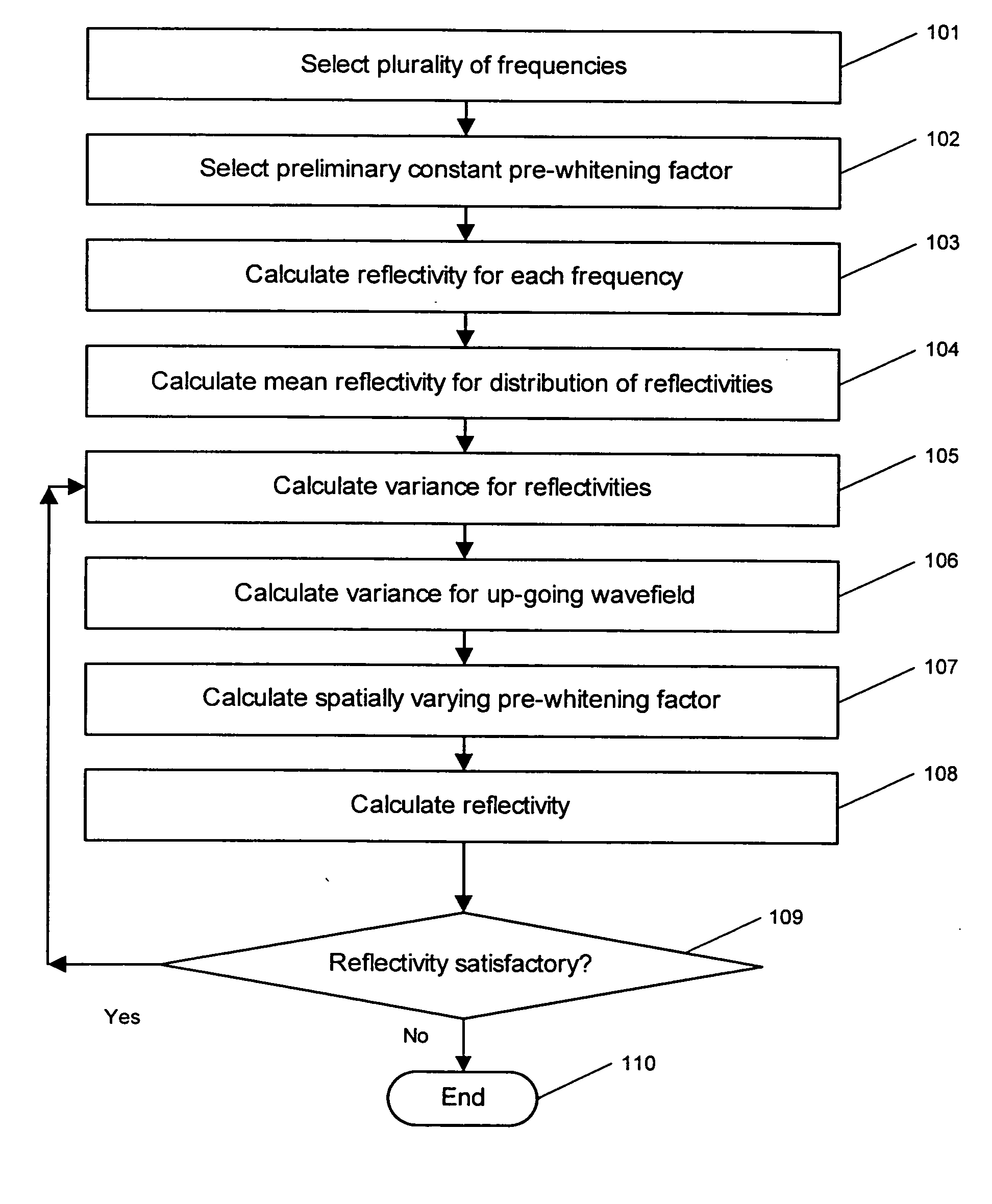
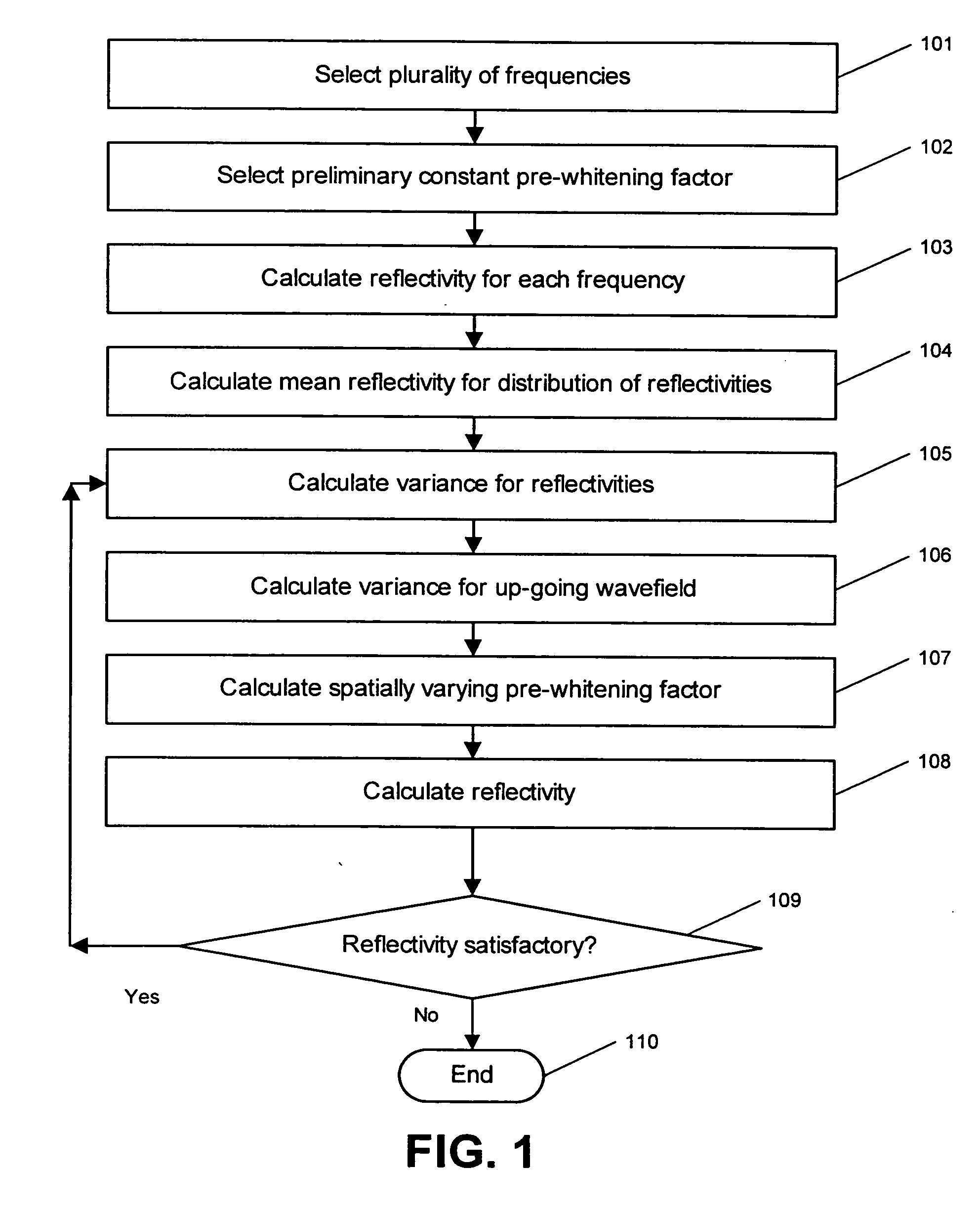
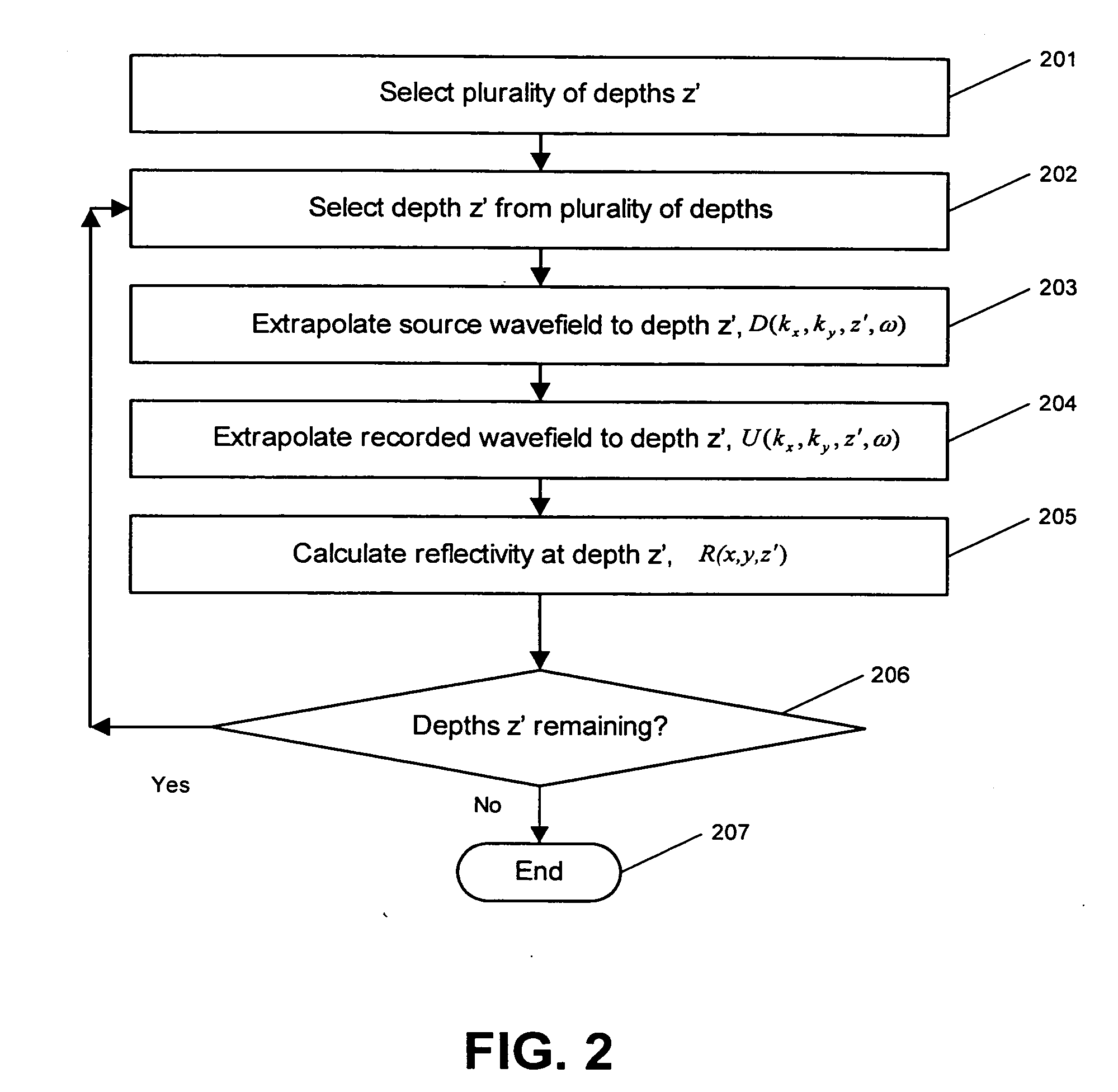
[0032] The invention is a method for imaging prestack seismic data. The method of the invention is illustrated by two embodiments. The first embodiment is an iterative, non-linear inversion to solve for an optimum, adaptive, spatially variable pre-whitening factor. The second embodiment is a least-squares inversion to determine the optimum reflectivity for the set of all frequencies at each depth.

[0033] At each depth and at each lateral coordinate, a dynamic (amplitude-based) imaging principle is applied in order to compute an estimate for the reflection coefficient. One of two imaging methods can be used. The first imaging method computes an average over the set of results for all “upgoing over downgoing” computations, with an added pre-whitening factor in the denominator that automatically adapts to the noise conditions at each location. The adaptation is accomplished by iteratively computing variance estimates for the “data” (receiver wavefield) and “model” (reflectivity). The s...


PUM

PropertyMeasurementUnit
reflectivityaaaaaaaaaa
frequencyaaaaaaaaaa
mean reflectivityaaaaaaaaaa

Abstract

Prestack seismic data is imaged by calculating an individual reflectivity for each frequency in the seismic data. Then, a mean reflectivity is calculating over the individual reflectivities. A variance is calculated for the set of reflectivities versus frequency. A second variance is calculated for the upgoing wavefield, using the mean reflectivity. A spatially varying pre-whitening factor is then calculated, using the variance for the reflectivities and the variance for the upgoing wavefield. A reflectivity is calculated at each location, using the spatially varying pre-whitening factor.

Description

CROSS-REFERENCES TO RELATED APPLICATIONS [0001] Not Applicable FEDERALLY SPONSOR RESEARCH OR DEVELOPMENT [0002] Not Applicable SEQUENCE LISTING, TABLE, OR COMPUTER LISTING [0003] Not Applicable BACKGROUND OF THE INVENTION [0004] 1. Field of the Invention [0005] This invention relates generally to the field of geophysical prospecting. More particularly, the invention relates to the field of seismic data processing. Specifically, the invention is a method for imaging prestack seismic data for seismic migration. [0006] 2. Description of the Related Art [0007] Seismic migration is the process of constructing the reflector surfaces defining the subterranean earth layers of interest from the recorded seismic data. Thus, the process of migration provides an image of the earth in depth or time. It is intended to account for both positioning (kinematic) and amplitude (dynamic) effects associated with the transmission and reflection of seismic energy from seismic sources to seismic receivers....

Claims


Application Information

Patent Timeline
Patent Type & Authority Applications(United States)
IPC IPC(8): G01N1/28G01V1/00G01V1/28G01V1/32G01V1/36G06K9/00G06K11/06G09G5/00
CPCG01V2210/57G01V1/28
Inventor KELLY, STEVE MICHAEL
Owner PGS AMERICA INC
Why Eureka
Try Eureka