Band switchable type tuning circuit of television signal

Inactive Publication Date: 2005-05-26
ALPS ALPINE CO LTD
View PDF12 Cites 2 Cited by
  • Summary
  • Abstract
  • Description
  • Claims
  • Application Information

AI Technical Summary

Benefits of technology

[0020] Further, the first switch means, the second switch means, the second resistor, and the third resistor

Problems solved by technology

Therefore, there are problems in that an on resistance of the switch diode is high and a Q of the VHF input tuning circuit 22 is lowered.
Therefore, there are pr

Method used


Image

  • Band switchable type tuning circuit of television signal
  • Band switchable type tuning circuit of television signal
  • Band switchable type tuning circuit of television signal

Examples


Embodiment Construction

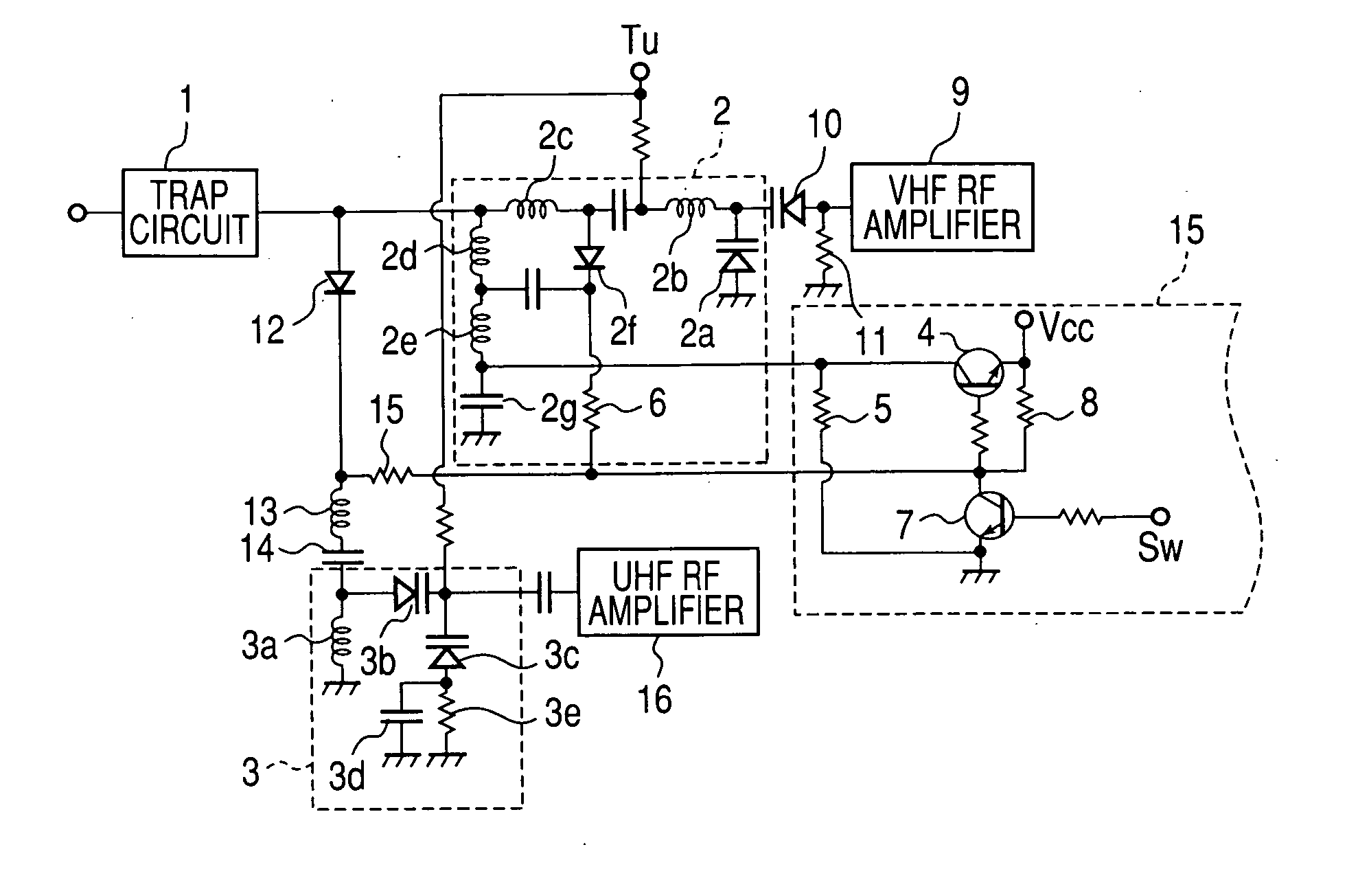
[0026]FIG. 1 shows a band switchable type input tuning circuit according to the present invention. Television signals of a VHF band and a UHF band are input to a VHF input tuning circuit 2 and a UHF input tuning circuit 3 via a trap circuit 1 which eliminates unnecessary signals such as FM broadcast signals.

[0027] The VHF input tuning circuit 2 has a tuning varactor diode 2a whose anode is grounded, four coils, that is, a high-band coil 2b, a low-band coil 2c, a low-band coil 2d and a high-band coil 2e, which are sequentially connected in series to a cathode of the tuning varactor diode 2a in radio frequency wise and which are connected in parallel to the tuning varactor diode 2a in radio frequency wise, and a switch diode 2f which extends over the two low-band coils 2c and 2d and which are connected in parallel thereto in radio frequency wise. The high-band coil 2e of a low potential side is grounded via a direct current (DC)-cutting capacitor 2g in radio frequency wise. Here, to ...


PUM


Abstract

A band switchable type tuning circuit has first switch mean interposed between a power supply Vcc and an anode of a switch diode, a first resistor whose one end is connected to a cathode of the switch diode, second switch means interposed between the other end of the first resistor and a ground, a second resistor connected between the power supply Vcc and a connection point of the first resistor and the second switch means, and the third resistor connected between the ground and a connection point of the first switch means and the anode of the switch diode. The first switch means and the second switch means are turned on or off together by means of a band switching voltage.

Description

BACKGROUND OF THE INVENTION [0001] 1. Field of the Invention [0002] The present invention relates to a band switchable type tuning circuit which is adapted to tune to television signals of a high band or a low band. [0003] 2. Description of the Related Art [0004]FIG. 5 shows a conventional band switchable type input tuning circuit. Television signals of a VHF band and a UHF band are input to a VHF input tuning circuit 22 and a UHF input tuning circuit 23 via a trap circuit 21 which eliminates unnecessary signals such as FM broadcast signals. [0005] The VHF input tuning circuit 22 has a tuning varactor diode 22a whose anode is grounded, four coils, that is, a high-band coil 22b, a low-band coil 22c, a low-band coil 22c and a high-band coil 22d, which are sequentially connected in series to a cathode of the tuning varactor diode 22a in radio frequency wise and which are connected in parallel to the tuning varactor diode 22a in radio frequency wise, and a switch diode 22f which extends...

Claims


Application Information

Patent Timeline
IPC IPC(8): H03J3/18H03J3/28H03J5/24H04B1/18H04N5/44
CPCH03J3/185H04N5/4446H03J5/244
Inventor YAMAMOTO, MASAKI
Owner ALPS ALPINE CO LTD
Why Eureka
Try Eureka